168
Program description - Flight phase timers
Fl. phase timers
Selecting and setting
A description of how timers are assigned to a flight
phase has already been provided in the text for the
»Phase settings« menu, page 154 and 158. The
same section has also described the properties of
"Time1" and "Time2". This section now proceeds to
describe "Timer 1, 2 and 3" and the "lap counter/time
table" timer variants.
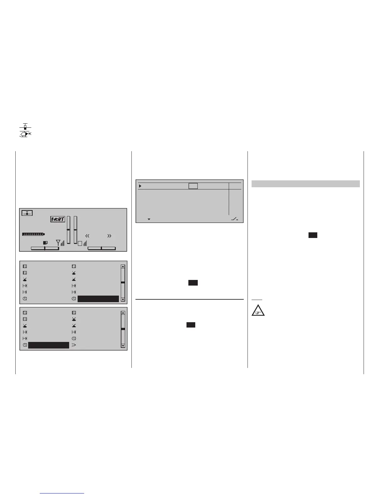
The additional, flight phase-specific timer selected is
displayed on the basic display underneath the "cen-
tre" timer, as shown below:
#01
0:00h
Stop watch
Flight tim
K78
0:00.0
4.1V
0:00.0
00
0
0
0:00h
M
V
Graubele
H-J Sandbrunner
Normal
Timer 1
00
0:00.0
RX VOLT:4.9V
On this menu …
Control adjust
Dual Rate / Expo
Channel 1 curve
Switch display
Control switch
Logical switch
Phase settings
Phase assignment
Phase trim
Non-delayed chan
Timers (general)
Fl. phase timers
Control adjust
Dual Rate / Expo
Channel 1 curve
Switch display
Control switch
Logical switch
Phase settings
Phase assignment
Non-delayed chan
Timers (general)
Fl. phase timers
Helicopter mixer
… you can now program "Clks 1 … 3" as stopwatches
(i. e. timers that run forward) or as countdown/alarm
timers (i. e. timers that run backwards). You can assign
any switch to these timers, and the same is true of the
"lap counter/timetable" timer:
Timer 1
Timer 2
Timer 3
Lap time/Tim tab
–––
0:00
0:00
0:00
Lap display
0s
0s
0s
–––
–––
–––
–––
AlarmTimer
The flight phase timers "Timer 1 … 3" and the
"Time1"/"Time2" timers (described in the »Phase set-
tings« section, pp. 154 and 158) run only in the flight
phase to which they have been assigned. They are
also shown as appropriate on the basic display. Dur-
ing other flight phases they are stopped (and hidden)
and the assigned stop/start switch then has no effect.
The lap counter, once started, continues to run
through changes of phase (as discussed further be-
low), however, although it can be stopped during any
flight phase via the centre ESC key of the left touch
pad.
Clks 1, 2 and 3
These timers are started and stopped via a switch or
control switch. To do so, first use the selection keys to
select the appropriate column via the switch icon at
the bottom right. Then set the switch that you want by
briefly tapping the centre SET key of the right touch
pad, as described in the section "Assigning transmit-
ter controls, switches and control switches" (p. 60).
Here, too, a control switch offers you the option of
activating the timer via one of the sticks or propor-
tional controls.
The switching point along the transmitter control
travel is set on the »Control switch« menu (page
146).
Remember that the timer switches also remain active
in programming mode.
Switching between "forwards" and "backwards"
Stopwatch mode (timer runs forwards)
In this mode, the timer starts at the initial value "0:00"
(min:sec) when you operate the assigned switch. If
it reaches the maximum time of 179 min. and 59 s, it
will re-start at "0:00".
"Countdown" (timer runs backwards)
Following the activation of the corresponding value
fields (by tapping the centre SET key of the right
touch pad), if a time in minutes (maximum 179 min)
and/or a time in seconds (maximum 59 s, right field)
is set, then the timers will run backwards from this
initial value following the activation of the assigned
switch (see section "Assigning transmitter controls,
switches and control switches" on page 60), i. e. a
"countdown" function will apply. Once the timer reach-
es zero it does not stop, however, but continues to
run (highlighted) so you can read off the time elapsed
after reaching zero.
Note:
Timers that are running backwards are shown
on the basic display with a ashing colon (:)
between the minutes and the seconds elds.
A simultaneous tap on the or keys of the right
touch pad (CLEAR) will reset entry values in the cur-
rently active field back to zero.