178
Program description - Wing mixers
Model type: "2AIL"
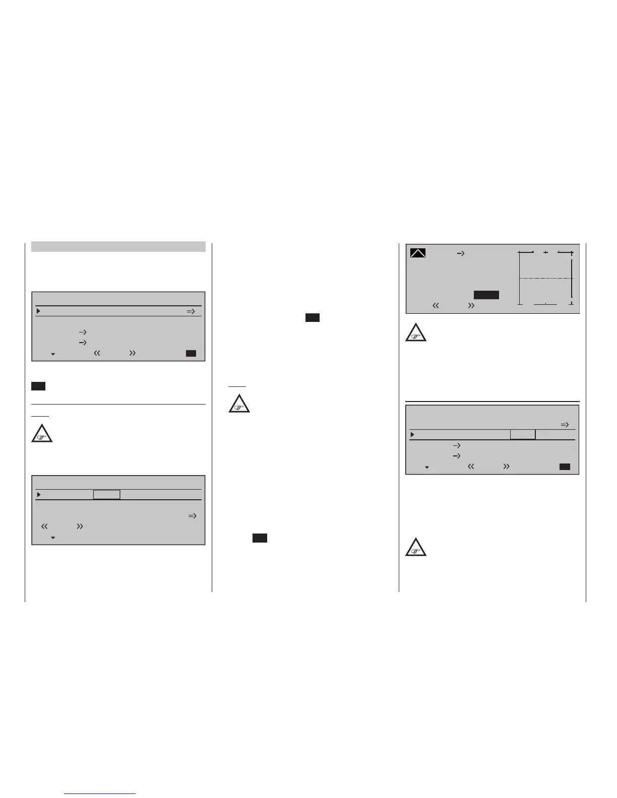
If you have entered "2AIL" for the "Aileron/camber
flaps" line on the »Model type« menu (page 105),
then the "Wing mixers menu" on your transmitter will
match the following screen image:
Aileron differential
Brake settings
0%
Aileron
0%
WING MIXERS
Elevator
aileron
0%0%
–––
–––
rudder
2
3
4
5
Normal
From the first line on this display screen, you can
switch to the sub-menu with a brief tap on the centre
SET key of the right touch pad …
Brake settings
Note:
The "Brake settings" menu is switched "off" if:
"Motor on C1 forward / back" in the »Model
type« menu (page 104) AND the "Motor"
column of the »Phase settings« menu, (page 154)
are set to "yes" for the currently active ight phase.
Switch the ight phase if required:
Elevator curve
BRAKE SETTINGS
Normal
Crow
AILE
0%
WK2
0%
WK
0%
Diff.- reduct
Depending on the model type selected, setting
options will now be available in the "Crow" and
"Diff(erential)reduct(ion)" lines for the column la-
beled "AILE". These options should be utilized by …
• … putting the transmitter control for "Brake" (re-
fer to the »Model type« menu description on
page 104) – typically the C1 stick – in its limit posi-
tion in the brake direction. Switch to the "Crow" line,
briefly tap on the centre SET key of the right touch
pad and use the selection keys on the left or right
touch pad to set a value that moves the aileron
upwards as far as possible to brake the model or, if
you are using airbrakes as the main braking sys-
tem, the aileron should be set to elevate only mini-
mally to provide an extra braking effect.
Note:
To reliably prevent the servos
mechanically striking their end-stops –
which draws a heavy current – you can
set an appropriate limit value in the column
labeled "– limit +" in the »Servo adjustment«
menu, page 112.
• … then finally, moving to the "Diff. reduct" line, set a
% value there which is greater than or equal to that
value set (or to be set) in the "Aileron differential"
line of the display screen "before" this one.
In this way, you can suppress the aileron
differential when braking, thus ensuring that you
can count on sufficient aileron response despite
your ailerons being deflected upwards.
From the lowest line, "Elevator curve", you can switch
to setting the "Elevator curve" mixer by briefly tapping
the centre SET key of the right touch pad:
Brake
Curve
off Point
Output
Input –100%
0%
L
+
–
100
O U T P U T
0%
Elevator
Normal
If required, i. e. if you have the feeling that you
will need to set pitch trim compensation when
the airbrakes are extended, you can program
an appropriate automatic mixer affecting the elevator at
this point.
For detailed instructions on setting a curve mixer,
please refer to the »Channel 1 curve« menu option
text beginning page 140.
Aileron differential
Aileron differential
Brake settings
0%
Aileron
0%
WING MIXERS
Elevator
aileron
0%0%
–––
–––
rudder
2
3
4
5
Normal
The adjustment range of ±100 % makes it possible to
set the correct direction of differential, regardless of
the direction of rotation of the aileron servos. While
"0 %" corresponds to a normal linkage, i. e. no trans-
mitter-side differential, "-100 %" or "+100 %" repre-
sents the "split" function.
For aerobatic flying, low absolute values are
required to ensure the model rotates exactly
along its longitudinal axis when an aileron
command is given. Values near to the centre (-50 % or
+50 %) are typical for facilitating turns in thermals.