118
Program description - Control adjust | Winged models
Control adjust
Basic procedure for transmitter control and switch assignment
Use the selection keys on the left or right touch pad
to scroll to the »Control adjust« option in the multi-
function menu:
Model select
Servo adjustment
Stick mode
Control adjust
Dual Rate / Expo
Channel 1 curve
Switch display
Copy / Erase
Suppress codes
Suppress models
Base setup model
Model type
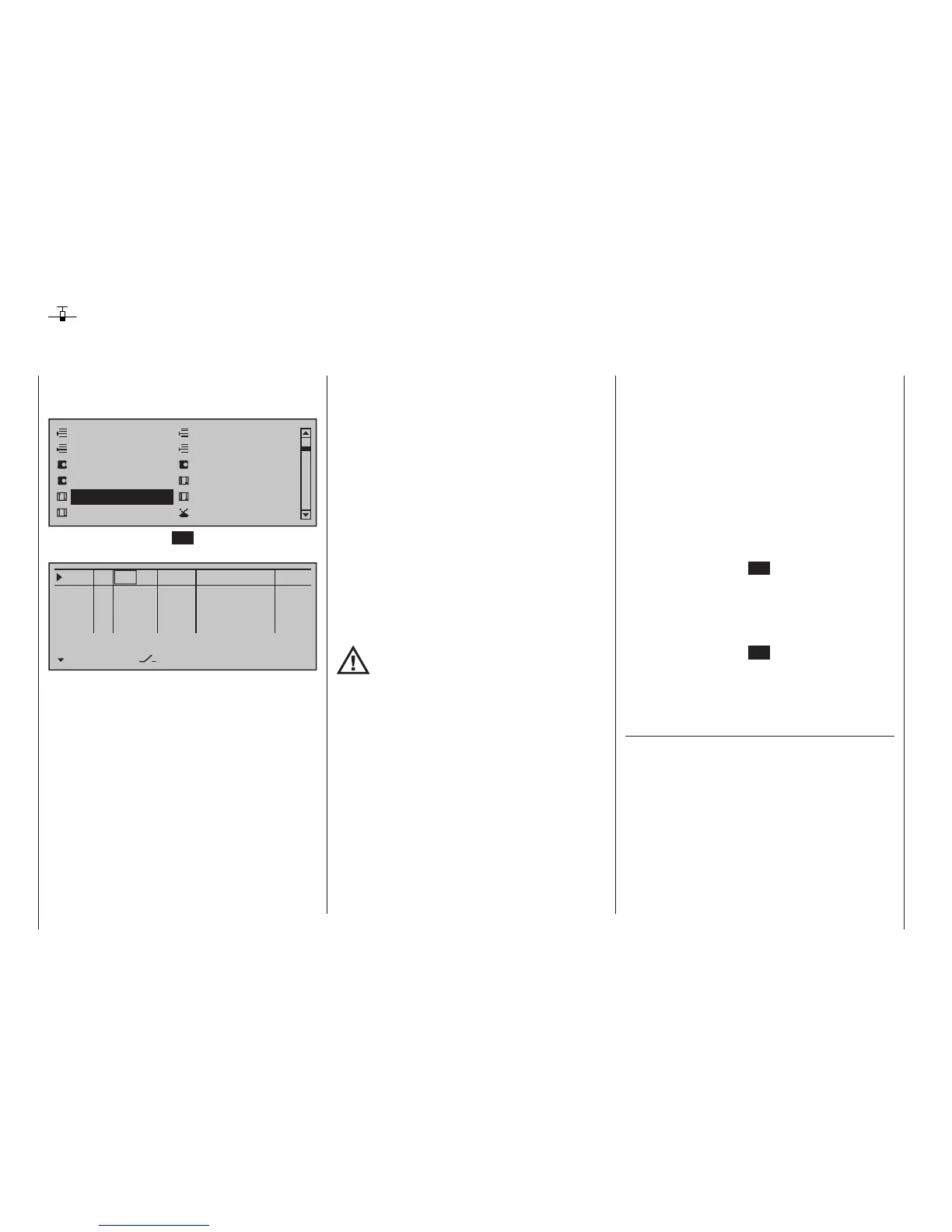
Tap briefly on the centre SET key of the right touch
pad to open this menu option:
0%
+100%I5
I6
I7
I8
TYP
SEL
+100%
0.0 0.0
– travel + –time+
0%
+100%
+100%
0.0 0.0
0%
+100%
+100%
0.0 0.0
0%
+100%
+100%
0.0 0.0
GL
GL
GL
fr ---
fr
fr
fr
---
---
---
Offset
GL
Normal
In addition to the two sticks for control functions 1 to 4
and their trim wheels, the mc-32 HoTT transmitter
also has other controls as standard equipment:
• two 3-way switches
• two 2-way switches
• two unlockable 2-way switches
• two self-restoring 2-way switches
• three proportional sliders on the middle console,
designated Sl 1 … 3 in the menu
• two side-mounted "rotary sliders", designated Lv1
and 2 in the menu
• two depressible "rotary controls", designated Tv2
and 4 in the menu
• three roller-shaped rotary controls, designated as
Tv1, Tv3 and Tv5 in the menu
In contrast to the two sticks which, when initialized for
a new model memory as a "Winged aircraft" model
type will already be configured to operate the servos
connected to receiver outputs 1 … 4, these "other"
operating elements initially remain inactive.
Thus, at least in the system's delivered state – as
already mentioned on page 68 – or even after ini-
tialization of a new model memory with an "aircraft"
model type and its "binding" to the receiver intended
for installation, only those servos connected to the
two sticks by way of receiver outputs 1 … 4 are able
to be operated; any servos which may be connected
to receiver outputs 5 … 16 will initially remain inactive
in their middle positions.
While this may appear a bit awkward at first glance
… this is the only way to ensure a completely free
selection from among "additional" operating elements
while, at the same time, not requiring the "deactiva-
tion" of unused operating elements. This is because:
The only way to ensure an unused operat-
ing element can have no effect on the
model, even if operated by accident, is to
make it inactive, i. e. not assigned to any function.
All of the aforementioned operating elements can
be freely assigned in this »Control adjust« menu to
any function input, see page 58, just to accommo-
date personal requirements. Equally, this also means
that each of these operating elements can also be
assigned to multiple functions at the same time, as
needed. For example: the exact same toggle switch
assigned to an input in this menu can, at the same
time, also have an assignment in the »Timers (gen-
eral)« menu, page 164, as an "On/Off" switch, etc.
Furthermore, all inputs can be selectively set to glob-
al or ight-phase specic operation if they have been
defined for flight-phases in the »Phase settings«
menu, page 154, and »Phase assignment« menu,
page 160. The names assigned to given flight phases
then appear in the second-from-the-bottom display
line, e. g. «Normal».
Basic procedure
1. Use the selection keys of the left or right
touch pad to select the desired input, "I5 … I16".
2. If necessary, use the selection keys of the
left or right touch pad to change to the desired
column.
3. Briefly tap the centre SET key of the right touch
pad. The corresponding input field is shown
highlighted.
4. Operate the chosen operating element or set the
desired value with the selection keys of the right
touch pad.
5. Briefly tap the centre SET key of the right touch
pad to complete data entry.
6. A simultaneous tap on the or keys of the
right touch pad (CLEAR) will any setting made
back to its respective default value.
Column 2, "TYP"
Similar to the previously described »Stick mode«
menu, this column can be used to define whether
further settings for the given input are to have a
"GL(obal)" or a "PH(ase-specific)" effect. Do this by
using the selection keys of the left or right touch pad
to select the desired input 5 through 16 in the column
labeled "TYP".