206
Program description - Helicopter mixer / Auto-rotation setting
Helicopter mixers
Auto-rotation setting
Auto-rotation permits both full-size and model heli-
copters to land safely in a crisis, e. g. if the motor
should fail. Moreover, if the tail rotor should fail, cut-
ting the motor and landing using auto-rotation is also
the only possible way to avoid a high-speed, uncon-
trollable rotation around the vertical axis and a result-
ing catastrophic crash – which is why a switchover TO
the auto-rotation phase takes place immediately.
Firmware version V1102 and lower
When the switchover to the auto-rotation phase is
made, the Helicopter mixer menu screen changes as
follows:
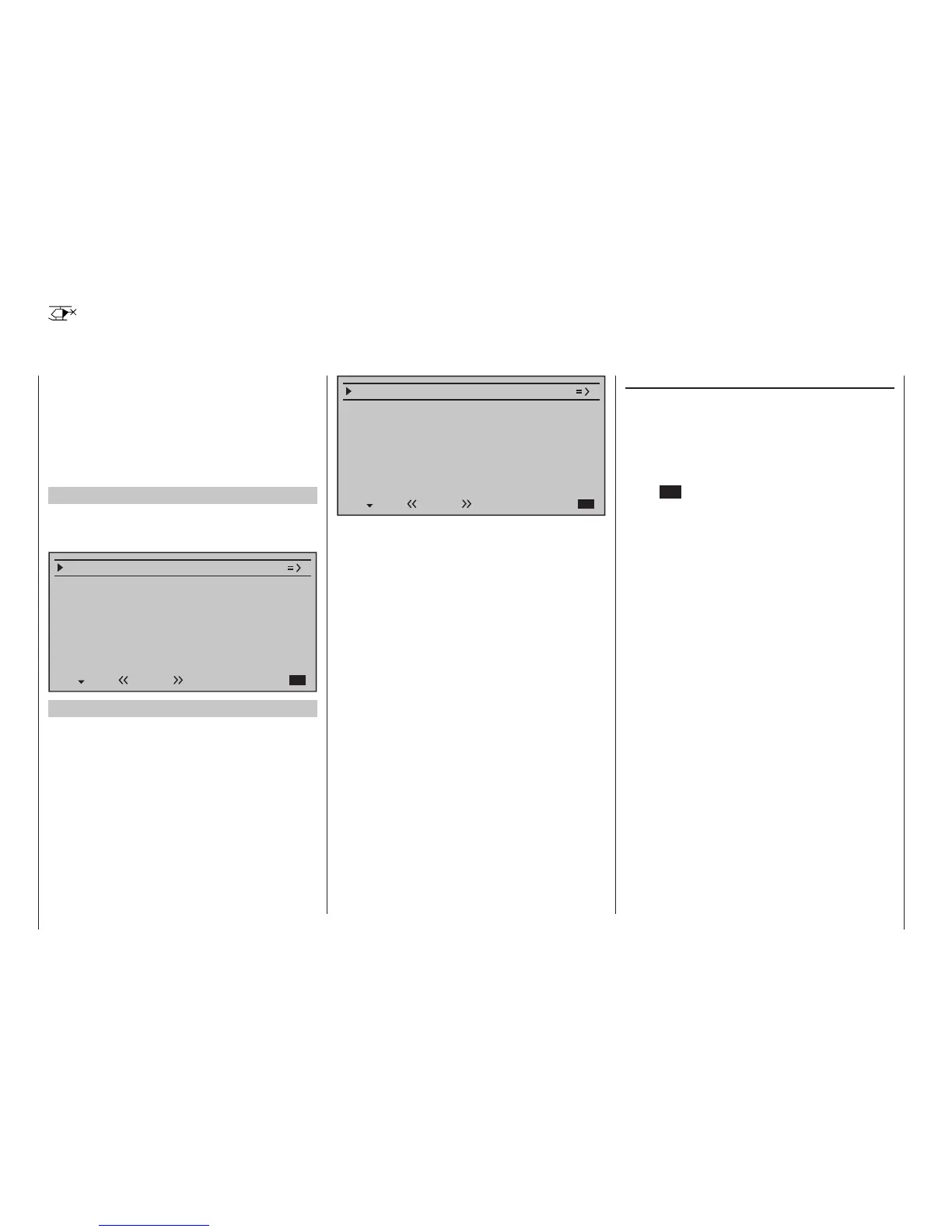
Pitch
–90%
Tail rot. offset AR
0%
Thr. position AR
Gyro suppression
Swashplate rotation
Swashplate limiter
0%
0°
off
Gyro offset 0%
Autorot
Firmware version V1102 and higher
Following the trend for electric helicopters, the default
value in the line “AR throttle position” a newly initial-
ized model memory is now -100%:
Pitch
–100%
Tail rot. offset AR
0%
Thr. position AR
Gyro suppression
Swashplate rotation
Swashplate limiter
0%
0°
off
Gyro offset 0%
Autorot
During auto-rotation flight, the main rotor is no longer
driven by the motor but only by its own momentum
and the airflow through the rotor plane during descent.
Since the energy stored by a rotor kept spinning in this
way is rapidly consumed if the helicopter flares, pilots
must not only have experience in handling helicopter
models but must also consider carefully how the rel-
evant functions should be configured.
The advanced pilot should therefore practice auto-
rotation landings at regular intervals. Not only to be
able to demonstrate mastery of the maneuver at
competitions, but also to ensure the pilot can land the
helicopter undamaged from a great height if the mo-
tor should fail.
For this purpose, the program provides a range of
adjustment options designed to help the pilot fly a
motorized model in its unpowered state.
Note that the auto-rotation settings comprise a com-
plete eighth flight phase, which provides access to all
the flight phase-specific configuration options, and to
trims, collective pitch curve settings, etc., in particu-
lar. The following functions have special features not
present in the powered flight phases:
Pitch (Collective pitch curve (C1 Pitch))
In powered flight, the maximum blade pitch angle
is limited by available motor power. In auto-rotation,
however, it is limited only by the point at which airflow
ceases over the main rotor blades. Greater maxi-
mum collective pitch must therefore be set to ensure
sufficient thrust when flaring the helicopter even as
rotational speed is falling off. To do so, briefly tap the
centre SET key of the right touch pad to switch to the
"Pitch" graph page and then use the stick to move
the vertical line to point "H". Start by setting a value
that is about 10 to 20 % greater than your "normal"
maximum value for collective pitch. Initially, however,
do NOT set a value that is considerably greater than
for normal flight, since, if this is done, the behavior of
the collective pitch controls may then be very unfamil-
iar following the switchover. Indeed, there is a danger
that the pilot will oversteer during the flare and the
model will balloon: this will case the rotor speed to
collapse at a considerable altitude and the model will
then crash to the ground. The value can always be
readjusted later after flying some test auto-rotations.
The minimum value for collective pitch can differ from
that set for normal flight. This depends on the pilot's
usual style for normal flight.
For auto-rotation, however, always set a sufficiently
generous minimum value for collective pitch at point
"L" to ensure the model can be brought out of forward
flight at moderate speed into a descent at an angle
of around 60 … 70 degrees when collective pitch is
reduced to a minimum.
If, like most helicopter pilots, you have used this kind
of setting for normal flight anyway, then this value can
simply be transferred.
If, however, you normally let your model "fall" at a
shallower angle, then you should increase the value
at point "L", and vice versa.