215
Program description - Free mixers
6
Mix input
+20%
Offset
EL
Linear MIX 1
+20%
SYM ASY
SET
STO
–100%
If the offset, now -100 %, is reset to 0 % of control
travel by using selection key on the left or right
touch pad to select the SET field then tapping either
the selection key combination or on the right
touch pad (CLEAR), the following screen will appear:
6
Mix input
+20%
Offset
EL
Linear MIX 1
+20%
SYM ASY
STO
0%
SET
Asymmetric mixer ratios
In many cases, however, we require different mixer
values on each side of the mixer neutral point.
Do this by first resetting the offset of the mixer used
in the example, "6 EL" again to 0 %, if necessary,
refer to the figure above. Now select the ASY field
with the selection key on the left or right touch pad
then tap the centre SET key of the right touch pad. If
slider control Sl1, assigned to input 6 in this example,
is now moved in each corresponding direction, the
mixer ratios for each of the two control directions,
i. e. left and right of the established offset point, can
be adjusted with the selection keys of the right touch
pad:
6
Mix input Offset
EL
Linear MIX 1
SYM ASY
STO
0%
SET
–55%
–20%
Note:
If you are using a type "S N.N.*" switch
channel mixer you will need to actuate the
assigned switch. The vertical line then jumps
between the left and right side.
Setting curve mixers 9 … 12
These four curve mixers allow the definition of ex-
tremely non-linear mixer curves by placing up to six
freely positionable points between the two endpoints
"L" (low = -100 % control travel) and "H" (high =
+100 % control travel) along the control travel.
If you have already read the »Channel 1 curve« menu
(page 140 ... 143) description or about programming
8-point curves in the »Helicopter mixers« menu
(page 191), you can safely skip the following descrip-
tion.
Programming details
The control curve is defined by up to 8 points, known
as "reference points". In the default software configu-
ration, 2 reference points are already defined, namely
only the two end-points, "L" and "H"; see the next
screen image.
The following section applies to "any" mixer to which
we wish to assign a non-linear curve characteristic.
The examples shown in the following
section are merely illustrative, however,
and they do not represent real-life mixer
curves.
Setting reference points
When you move the transmitter control assigned to
the mixer input – here control function 8 – a vertical
line in the graph follows the movement between the
two end-points. The current control position is also
shown numerically on the "Input" line. The point at
which this line intersects with the curve in question
is named the "Output" and can be varied between
-125 % and +125 % by setting reference points; see
further below. This control signal acts on the mixer
output.
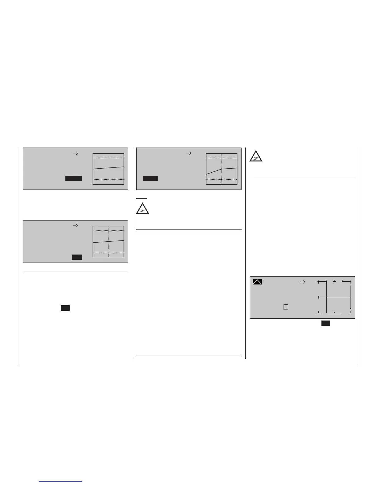
In the above example, the transmitter control is on
input 8 at -50 % of control travel. The output signal
continue to show 0 %, however, since no value has
yet been entered.
Up to six additional reference points can be set be-
tween the two end-points "L" and "H", although the
distance between neighboring reference points must
not be less than approx. 25 %.
Curve MIX 9
Curve
off Point
Output
Input –50%
0%
?
+
–
100
O U T P U T
0%
8
10
When you now briefly tap the centre SET key of the
right touch pad, the "?" is replaced by a point number
and the value field to the right is activated, i. e. pre-
sented in inverse video:
* N.N. = Nomen Nominandum (the name to be stated)