246
Program description - Telemetry
R-VOLT Current operating voltage of the
receiver in volts
L.R-VOLT Lowest operating voltage of the receiver
since it was last turned on, in volts
SENSOR1 Indicates values of optional telemetric
sensor 1, in volts and °C
SENSOR2 Indicates values of optional telemetric
sensor 2, in volts and °C
Signal quality (S-QUA)
The signal quality (S-QUA) is sent “live” over the
receiver’s return channel to the transmitter and indi-
cates the signal quality in %.
Reception power (S-dbm)
When specifying “dBm” is a logarithmic value for a
relatively clear indication of extremely large level
differences, where a level of 0 dBm corresponds to
a power of exactly 1 mW. Services> 1mW therefore
have positive dBm values, achievements <1mW
accordingly negative.
In the (remote control) practice, this means that, due
to the propagation of radio waves and the associated
attenuation of the signal on its way to the receiver,
for example, of the 100mW transmit power of a
standard-compliant transmitter (= 20dBm) usually
(considerably) less than 1 mW, and thus arrive at a
level <0dBm, the recipient. It follows that the appears
on the display in dBm specified reception level usually
with a negative sign. That but also:
The higher the following on the minus symbol
number, the worse the reception level! This is
important, among other things the range test before
starting the model operation.
Perform the range test as described on page 88 or
99 before each flight and, in doing so, simulate all
servo movements which also take place during the
flight. The range must be at least 50 m on the ground
with the range test activated. At this distance, the
value shown under “S-dBm” in the “RX DATAVIEW”
display may not be greater than -90 dBm in order to
guarantee safe operation. The model should never be
operated with a lower value (e. g. -95 dBm). Check the
installation of the receiver system and the position of
the antenna.
The reception power should not drop below -90 dBm
during operation. Otherwise, reduce the distance of
the model. Normally, however, the acoustic range
warning (peep tone interval 1 s) is triggered before
this value is reached in order to guarantee safe op-
eration.
Signal strength (S-STR)
The signal strength (S-STR) is displayed in %. In ge-
neral, an acoustic range warning (peep tone interval
1 s) is issued as soon as the receiver signal becomes
too week in the return channel. However, since the
transmitter has a significantly higher transmission
power than the receiver, the model can still be safely
operated. For the sake of safety, the distance to the
model should be reduced until the warning tone goes
silent again.
Receiver temperature (R-TEM.)
Make sure the receiver remains within the permissible
temperature range during all flight conditions (ideally
between -10 and 55 °C).
On the first display page...
RX DATAVIEW
... of the sub-menu “SETTINGS & DATAVIEW” of the
»Telemetry« menu, overwritten with …
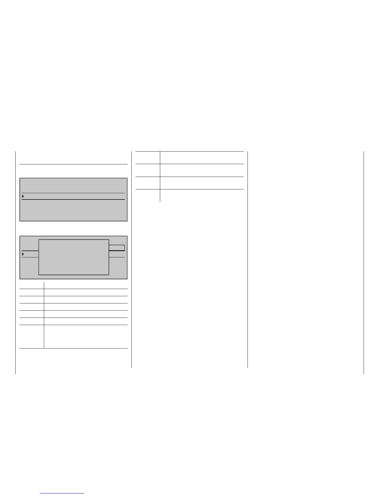
TELEMETRY
SETTING & DATAVIEW
SENSOR SELECT
RF STATUS VIEW
VOICE TRIGGER
TELEMETRY RCV
BIND. 1
… no settings can be made. This page is only pro-
vided for information:
TELEMETRY
SETTING & DATAVIEW
SENSOR SELECT
RF STATUS VIEW
VOICE TRIGGER
TELEMETRY RCV
BIND. 1
RX DATAVIEW
S–STR100% R–TEM.+28°C
L PACK TIME 00010msec
R-VOLT :05.0V
L.R-VOLT:04.5V
S–QUA100%S–dBM–030dBM
SENSOR1 :00.0V 00°C
SENSOR2 :00.0V 00°C
Value Explanation
Vx.xx Receiver’s firmware version
S-QUA Signal quality in %
S-dBm Reception power in dBm
S-STR Signal strength in %
R-TEM. Receiver temperature in °C
L PACK
TIME
Indicates the time in ms in which the
longest data package is lost during the
transmission from the transmitter to the
receiver
SETTINGS & DATAVIEW