320
Programming examples - Delta and ying wing
Of course, the general comments regarding the in-
stallation and the adjustment of the RC system to a
model at the beginning of the wing model program-
ming on page 288 also applies for delta and flying
wing models! Similarly, the comments for test flying
and fine-tuning the settings to the programming of
flight phases also apply.
left
right
Delta and flying wing models differ significantly from a
"normal" flight model due to their unique characteris-
tic shape and geometry. The differences in the servo
arrangement, on the other hand, are more subtle. For
example, with "classic" delta/flying wing models, only
two rudders are normally provided. They are respon-
sible for both "transverse" and "height/depth", like the
side rudder/elevator function on a V-tail unit.
With more elaborate designs, on the other hand, it
may be the case that one (or two) interior rudders
have only an elevator function and the exterior ai-
lerons only support the height/depth function, under
certain circumstances. Even with a 4, or indeed up
to 8, flap wing the use of camber flap functions and/
or even a crow system is nowadays entirely possible.
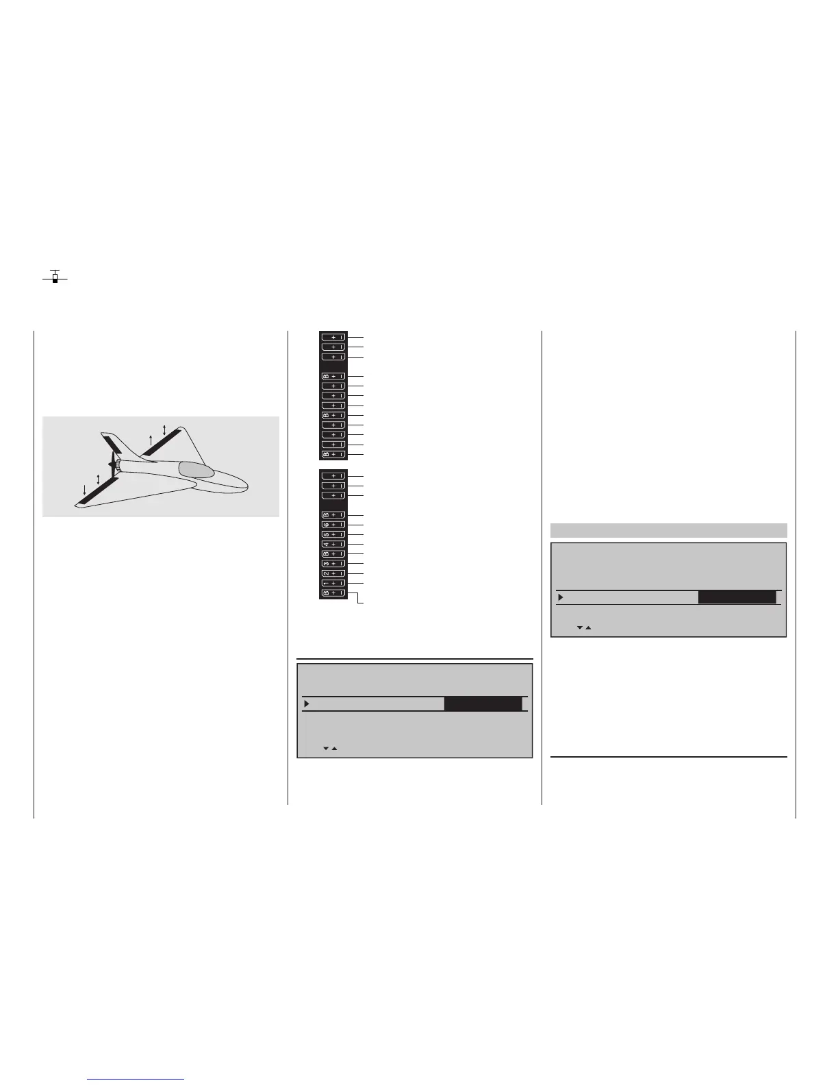
In all these cases, however, the following assignment
of the receiver outputs should be used, see also
page 65. Unneeded outputs a simply left free:
Receiver power supply
Receiver power supply
Airbrake- or throttle servo
or speed controller (electric motor)
13 14 T
15 16
S
77
8
9
10 11 12
Receiver power supply
Telemetry connection
Receiver power supply
free or aux. function
free or aux. function
SUMO / SUMI-connection
Receiver power supply
Receiver power supply
free or aux. function or AIL2 / left EL
free or aux. function or AIL2 / right EL
free or aux. function
free or flap / left elevator
free or flap / right elevator
free or aux. function or flap2 / left EL
free or aux. function or flap2 / right EL
free or aux. function
free or aux. function
AIL / elevator left
AIL / elevator right
free or aux. function
free or rudder
According to the assignment of the receiver outputs,
in the menu …
»Model type« (page 94)
Tail type
Motor on C1
none
Aileron/camber flaps
2 AIL
M O D E L T Y P E
Brake Offset Input 1+100%
SEL
Delt/fl.wing
… the necessary settings are made:
• “Motor an C1”
“none” or “Throttle min front/rear”
Delta and ying wing
• “Tail type”
“Delt/fl.wing”
• “Aileron/camber aps”
“2AIL” (appears automatically).
To the extent necessary, expand default “2 AIL” by
4 AIL or 1, 2 or 4 camber flaps (“1 FL”, “2 FL” or “4
FL”).
• “Brake”
stays as is, only interesting for a delta wing or
flying wing of type “2/4 AIL 1/2/4 FL”. In this case,
refer to the text under “Brake offset” on page 105.
These model type specifying settings primarily affect
the functions made available in the »Wing mixers«
menu. Therefore, the options are discussed separately
for two-flap and multi-flap models in the following:
Delta/ying wing of the type: "2AIL"
Tail type
Motor on C1
none
Aileron/camber flaps
M O D E L T Y P E
Brake Offset Input 1+100%
SEL
Delt/fl.wing
2 AIL
By retaining the standard default "2 AIL" in the "Ai-
leron/camber flaps" line, elevator and aileron control,
including the trim function, are automatically mixed
by percentage on the software side. However, on the
transmitter side, the percentage effect of the elevator
and aileron stick can be influenced in the »Dual Rate
/ Expo« menu, page 132.
Settings in the menu …
»Wing mixers« (beginning page 172)
… are, if need be, advantageous with the "Aileron
Rudder" mixers and are "played' with a great deal
of "feel" for flying behavior with minor differentiation
values.