40
Transmitter description - Telemetry data display
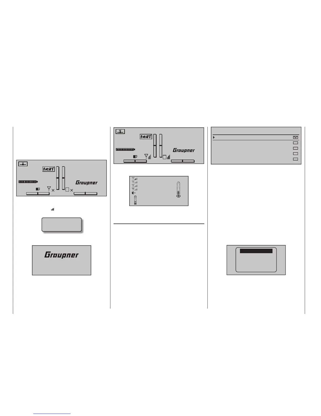
The
mc-32 transmitter has two independent dis-
plays; a large display for operating the transmitter and
a smaller display just below the antenna socket for the
graphic display of telemetry data. The telemetry dis-
play is activated automatically as soon as the trans-
mitter receives telemetry data from the receiver via
the return channel.
#01
0:00h
Stopwatch
Flight tim
K78
0:00.0
4.1V
0:00.0
00
0
0
0:00h
M
V
If however, at the lower edge of the base display, only
"X" – as shown in the fi gure above – is displayed at two
locations instead of " " then the telemetry display will
show the warning …
CAN‘T
RECEIVE
DATA
… which will be replaced shortly thereafter with the
Graupner|SJ logo and the transmitter names …
mc32
… to indicate there is no receiver with a respond-
ing telemetry connection within range. Switch on the
model's receiver system or bind a receiver to the ac-
tive model memory as described in detail on page 84
and 94.
#01
0:00h
Stop watch
Flight tim
K78
0:00
4.1V
0:00
00
0
0
0:00h
M
V
RX VOLT:4.8V
When a telemetry connection exists, the upper display
will automatically present the "Receiver" screen …
RX–S QUA: 100%
RX–S STR: 100%
TX–dBm: 33dBm
RX–dBm: 33dBm
RX–VOLT:4.8 TMP
L–PACK: 10ms
CH OUTPUT TYPE:ONCE
R-LOW V:4.6 +22°C
… which is described in more detail in a section by
the same name on the next page.
Sensor(s)
Up to four sensors can be connected, in any combina-
tion, to a telemetry-capable receiver.
The data output of these sensors in the graphic dis-
plays described below must be accepted if they have
been properly connected before turning on the receiver
on this and afterwards also recognized automatically
via the return channel from the transmitter.
For transmitters
mc-32 HoTT with fi rmware version
number lower than V1.050 the “Telemetry” data output
by these sensors must be (as described on page 258)
selected in the »SENSOR SELECT« sub-menu of the
»Telemetry« menu …
SENSOR SELECT
RECEIVER
GENERAL MODULE
VARIO MODULE
ELECTRIC AIR.MOD
GPS
… to activate the sensors accordingly. Likewise, it
must be ensured that the intended recipient in the line
“module” of the menu “Basic adjustment model” (page
83 or 94) bound as described and selected according
to the line “TEL.RECEIVER” of the “Telemetry” menus
(Bind 1 ... 4) and also turned on. If necessary, an-
other receiver selected, only the data in the “receiver”
screen will be displayed.
Furthermore, only sensors activated in the »SET-
TING & DATAVIEW« sub-menu of the »Telemetry«
menu, beginning page 246, according to the instruc-
tions included with the given sensor will be respon-
sive.
To switch between the screens for activated sensors
in the »SENSOR SELECT« sub-menu of the »Telem-
etry« menu, tap briefl y on one of the selection
keys of the left or right touch pad …
RX–S QUA: 100%
RX–S ST : 100%
TX–dBm: 33dBm
RX–dBm: 33dBm
RX–SPG.:4.8 TMP
V–PACK: 10ms
CH OUTPUT TYPE:ONCE
GENERAL
ELECT. AIR
VARIO
GPS
RECEIVER
… and, after the selected screen has been displayed,
use one of the two keys to select the line of the
desired sensor. If no sensor is activated, then all dis-
play lines and sensors described in the next column,
except for the "RECEIVER" line, are blended out of
the display and the selection list:
Telemetry data display