312
Programming examples - Using ight phases
Example 2 …
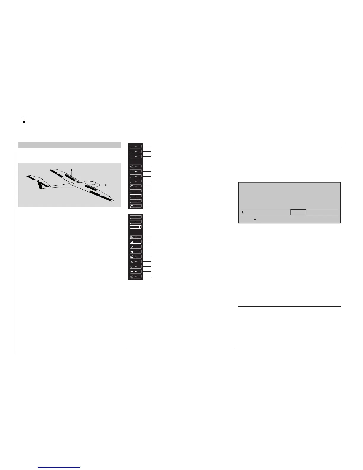
Glider with four ap wings, two large aps and
tow coupling
AI
FL
FL
AI
EL
RU
The following example is based on the assumption
that you have already mechanically pre-adjusted the
model and you have already ensured the correct
deflection of all rudders or checked this again in the
scope of this programming and made adjustments,
if applicable, through servo switching at the receiver
and/or through the »Servo adjustment« menu.
This programming example is based on an assign-
ment of the receiver connections in accordance with
the following diagram:
Receiver power supply
free or aux. function
free or aux. function
Rudder or elevator/rudder right
Left aileron
Elevator or elevator/rudder left
2nd airbrake or free or aux. function
Receiver power supply
Airbrake or 1st airbrake
Right aileron
Left flap
Right flap
Aero-tow release or free or aux. function
free or aux. function
13 14 T
15 16
S
77
8
9
10 11 12
Receiver power supply
free or aux. function
free or aux. function
Telemetry connection
Receiver power supply
free or aux. function
free or aux. function
SUMO / SUMI-connection
Receiver power supply
Receiver power supply
Begin with the new programming of the model in a
free model memory location.
Essentially, the »Base settings« menu is used to
bind the receiver to the transmitter. Enter a model
name and select or review the selection of appropri-
ate stick mode. Later on this menu will also be used
to activate the range test before the start of flight
operations.
In the menu …
"Model type" (page 104)
… leave "Motor to C1" at "none" and the tail type at
"Normal". Set "2 AIL 2 FL" into the "Aileron/flaps" line.
In the "Brake Offset" line, program or leave "Input 1",
because the brake and spoiler flap servos connected
to 1 + 8 should be activated later with the correspond-
ing C1 stick as the control:
Tail type
Motor on C1
Normal
none
Aileron/camber flaps
2AIL 2FL
M O D E L T Y P E
Brake Offset Input 1+90%
SEL
STO
The setting in the "Brake Offset" value field defines
the neutral position of all mixers specified by the
"Brake settings" sub-menu of the »Wing mixers«
menu. Place this neutral point at approx. +90 %,
insofar as the brake system should be retracted in the
front position of the C1 stick. The remaining path be-
tween +90 % and the full throw of the sticks, +100 %,
is then assigned as idle travel. This assures that the
rudders or flaps addressed by the mixers of "Brake
settings" remain in their "normal" positions even for
slight deviations from the limit position of the C1
control. At the same time, the effective control path is
automatically spread to 100 %.
In the menu …
»Control adjust« (page 118)
… assign a switch, for example Input 9, to operate
the aero-tow coupling. In order for this switch to work
independently of the flight phase, leave the standard
default "GL" in the "Type" column of this input. With
"– Travel +" you can adjust the control travel for the
switching of the switch:
Using ight phases