324
Programming examples - F3A model
F3A model
F3A models are a part of the group of motor-driven
winged models. They are powered by a combustion
or electric motor. Models with electric motors can be
used in both the electric acrobatic class F5A and are
also competitive in the international model acrobatic
class F3A.
The basic comments and notices for the mechanical
installation of a remote steering system, which was
already referred to in the first programming example
on page 288, also applies, of course, for F3A models
and does not need to be mentioned here again.
Faultlessly constructed F3A models exhibit a largely
neutral flying behavior. Ideally, they react with a good
nature but precisely to control movements without the
individual flight axes influencing one another.
F3A models are controlled with ailerons, elevator and
rudders. Normally, each aileron is actuated by a sepa-
rate servo. There is also the regulation of the drive
output of the motor (throttle function) and a retract-
able landing gear in many cases. The assignment of
the channels 1 to 5, therefore, do not differ from the
previously described winged models.
The additional "Retractable landing gear" function is
to be provided on one of the auxiliary channels 6 to
9. It is best to actuate the landing gear with a switch
without centre position. In addition, another mix offset
for the carburettor can – if necessary – be provided.
You normally use one of the three proportional con-
trols on the transmitter, which actuates one of the
unassigned auxiliary channels.
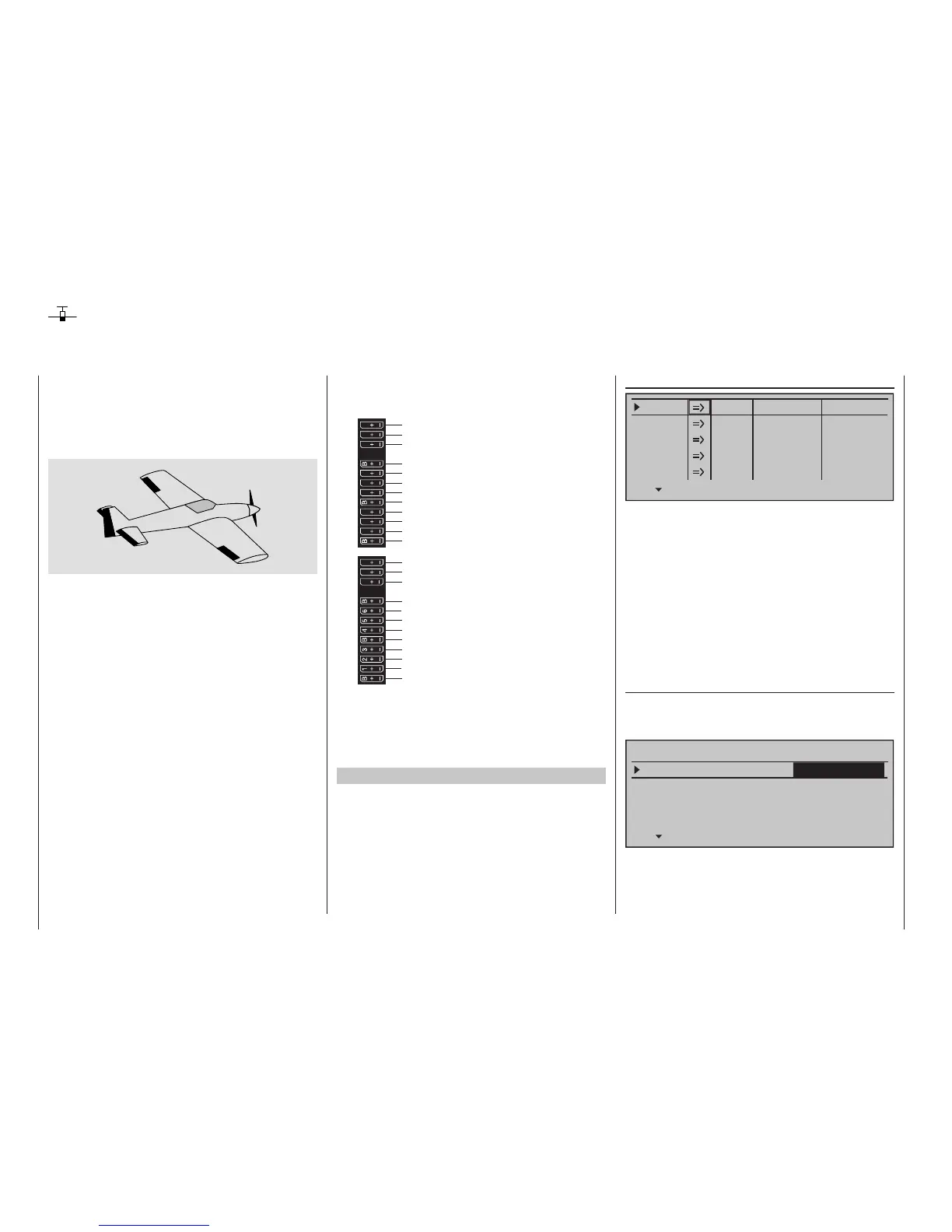
Receiver power supply
free or aux. function
free or aux. function
Rudder
Aileron or left aileron
Elevator or 1st elevator
free or 2nd elevator or aux. function
Receiver power supply
Throttle servo or speed controller (electric motor)
Right aileron
free or landing gear or aux. function
free or fuel mixture or aux. function
free or aux. function
free or aux. function
13 14 T
15 16
S
77
8
9
10 11 12
Receiver power supply
free or aux. function
free or aux. function
Telemetrieanschluss
Receiver power supply
free or aux. function
free or aux. function
SUMO / SUMI-connection
Receiver power supply
Receiver power supply
With the assignment of auxiliary channels at the
transmitter, we recommend making sure that the
operating elements required for this are easily within
reach, because during flight – especially in competi-
tion – you have "very little time" to release the stick.
Programming procedure
Since the basic programming of the transmitter was
already described in detail on pages 288 … 296, only
F3A-specific tips are added here.
In the menu …
»Servo adjustment« (page 112)
0%
100%Servo 1
Servo 2
Servo 3
Servo 4
Servo 5
Rev cent.
100%
150% 150%
– travel + – limit +
0%
100%
100%
150% 150%
0%
100%
100%
150% 150%
0%
100%
100%
150% 150%
0%
100%
100%
150% 150%
… the settings for the servos are carried out. Experi-
ence has shown that working with at least 100 % ser-
vo throw is beneficial, because the control precision
is significantly better if greater servo travel is used.
This should already be taken into account during the
construction of the model in the design of the rudder
linkages. Check the servo's direction of rotation. The
servo centre should be adjusted mechanically, insofar
as possible.
Any corrections can be made on the software side in
the third column during the initial test flights.
Through the menu …
"Model type" (page 104)
… the idle trim is activated for Channel 1 (normally
"rear", because full throttle is "front"). The trimming
then only works in the idle direction:
Tail type
Motor on C1
Normal
Aileron/camber flaps
1 AIL
M O D E L T Y P E
Brake Offset Input 1+100%
SEL
Thr. min rear
The remaining settings are made or left as shown in
the figure.