202
Program description - Helicopter mixer
Fine-tuning the throttle and collective pitch curve
Practical approach
Although the throttle and collective pitch control sys-
tems are based on separate servos, they are always
operated together by the throttle/pitch stick (except
during autorotation flight). This coupling is performed
by the helicopter program automatically.
In the
mc-32 HoTT program, the trim wheel of
control function 1 acts principally only on the throt-
tle servo. However, in the »Stick mode« menu (see
page 116) a decision can be made if this should
be used for idle trimming as part of the throttle limit
function, or for idle trimming during the auto-rotation
phase ("throttle AR").
The process of fine-tuning throttle and collective pitch,
i. e. setting the motor power curve to match the collec-
tive blade pitch setting, is the most important aspect
of setting up a model helicopter. The
mc-32 HoTT
software provides for independent configuration of
the throttle, collective pitch and torque compensation
curves, in addition to the C1 control curve (»Channel 1
curve« menu, page 143).
While these curves can be modelled using up to
eight points, fewer points are generally sufficient. We
recommend starting with three-point curves to begin
with. This involves setting individual values for the
centre point and other (optional) reference points, and
for the two end-points ("L", "low", and "H", "high") of
the throttle/collective pitch stick: together, these de-
fine the control curves.
Before setting the throttle and collective pitch func-
tion, the rods of all servos should be mechanically
pre-adjusted correctly according to the set-up instruc-
tions for the given helicopter.
Note:
The hover point should normally be
set to the centre position of the
throttle / collective pitch stick. In
special cases, e. g. for "3D" flight, deviating
hover points can also be programmed.
For example, one point for normal flight
attitude above the centre and one point for
inverted flight attitude below the centre.
Idle setting and throttle curve
Note:
Since electric drive systems have no need for
an idle setting, motor idling does not need to
be calibrated. Fine-tuning of the throttle and
collective pitch curve(s), however, must take place as
for glow-powered helicopters.
The idle setting, whose detailed description begins on
page 129, always takes place with the throttle limiter
closed – normally with the trim wheel of the C1 func-
tion and only in special cases is the throttle limiter
itself also utilized (as standard, the CTRL 6 propor-
tional rotary control).
The programming of a corresponding value for the "L"
point of the throttle curve acts to set the descent speed
of the motor, without influencing the hover configuration.
Here, for example, flight phase programming can be
used to set different throttle curves. This increased
system rotational speed below the hover point proves
to be useful in certain circumstances, e. g. for fast,
steep landing approaches with greatly reduced col-
lective pitch, and for aerobatics.
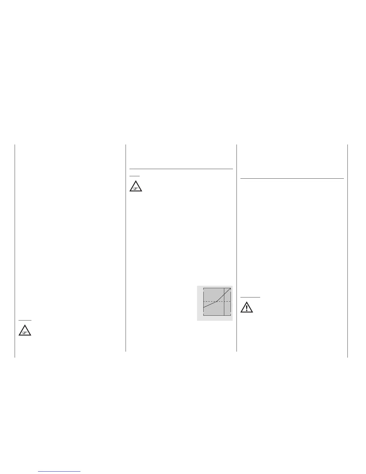
The figure depicts a curve with a
slightly changeable throttle setting
below the hover point at the control
centre.
+100%
-100%
OUTPUT
2 3 4 51
Control travel
Different throttle curves are programmed to be flight-
phase dependent in order to achieve the given opti-
mal adaptation to hovering flight as well as aerobat-
ics:
• Low system rotational speed with smooth, gentle
control response and low noise when hovering
• Higher rotor speed for aerobatics with motor power
set close to the maximum. In this case, the throttle
curve must also be adjusted in the hover range.
Basic set-up procedure
Even though pitch and throttle curves can be set elec-
tronically over a wide range with the
mc-32 HoTT
transmitter, all linkage in the model should already be
mechanically pre-adjusted correctly according to the
instructions for the given helicopter. Experienced heli-
copter pilots will be glad to help with this basic set-up.
The carburettor linkage must be set so that the throt-
tle is just past the fully open setting with collective
pitch set to maximum or, for electric helicopters,
with the speed controller set to full. When the throt-
tle limiter is closed, however, it must be possible to
just close off the carburettor using the C1 trim wheel,
without the servo mechanically striking its end-stop.
For electric helicopters, it must be possible to cut the
electric motor's speed controller safely with the throt-
tle limiter closed.
Take great care when configuring these settings, by
adjusting the control linkage as required and/or alter-
ing the linkage point on the servo or carburettor lever.
Only then should the throttle servo's fine-tuning be
electronically optimized.
Caution:
Inform yourself thoroughly about the
dangers and safety precautions
applicable to handling motors and
helicopters before starting the motor for
the first time!