54
Installation notices
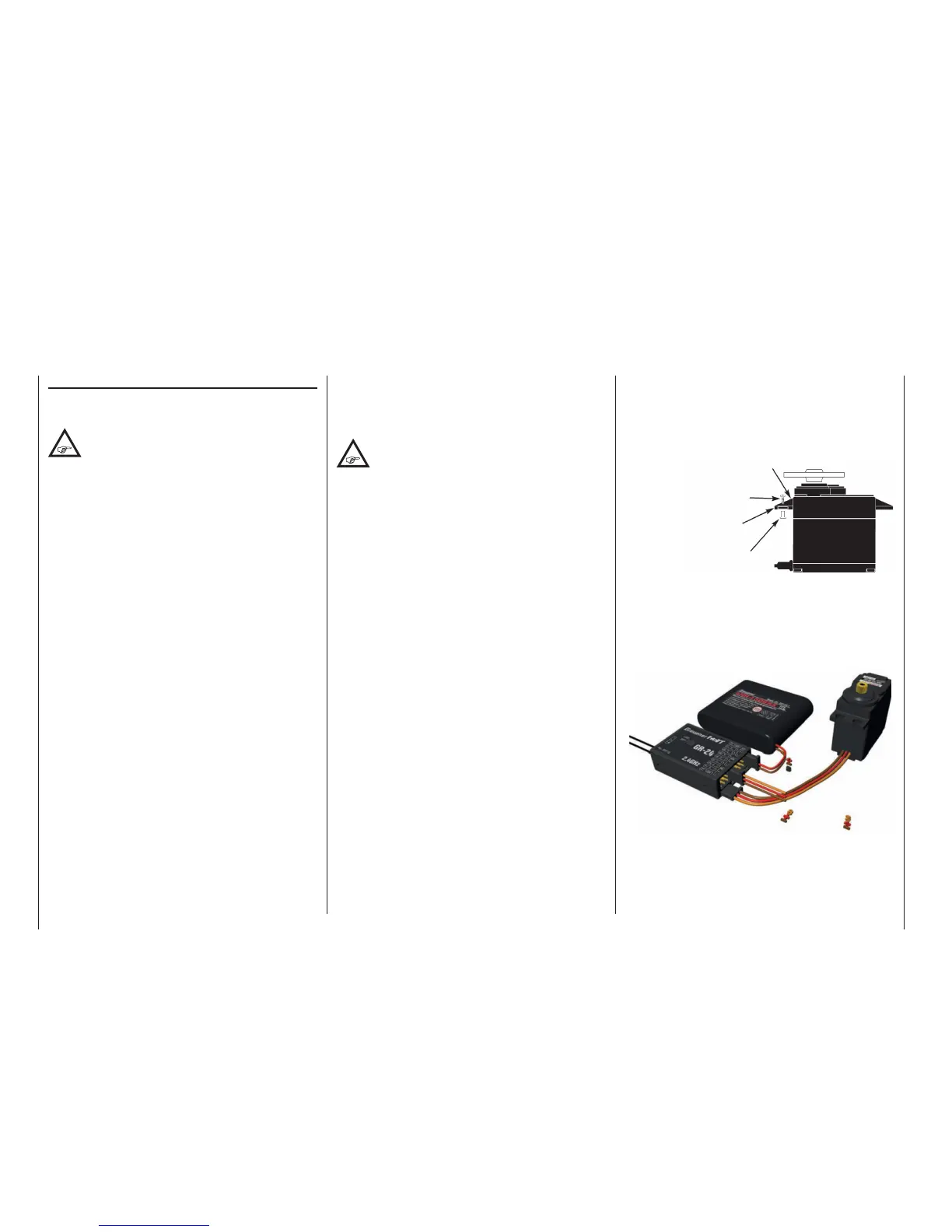
Only when servo fastening screws are properly
tightened will this arrangement provide security
and vibration protection for your servos. The figure
below shows how a servo is mounted properly.
The brass bearings are to be pushed into the
rubber bushes/spacers from below.
Servo mounting lug
Retaining screw
Rubber grommet
Tubular brass spacer
4. Servo arms must be free to move throughout their
entire range of motion. Pay attention that there are
no objects which could hinder servo arm motion.
5. Connect the power supply cable as well as the
power connection cables to the receiver as shown
below ...
In the also included in the set GR-12L receiver HoTT
, no specially designated connection for power supply
is available, so that the battery can generally be con-
nected to any free servo connection.
In the GR-12L receiver HoTT the terminals 1
... 6 are opposite respect to the GR-32 DUAL
receiver, it means they are installed rotated
by 180 degrees, which is why all the connecting
cables are „upside down“ to insert the GR-12L. If
necessary, is to use a V- or Y-cable (No. 3936.11).
The function of every individual channel is determined
by the transmitter used, not by the receiver. However,
channel assignments can be changed in the receiver
by programming done in the »Telemetry« menu.
Nevertheless, it is recommended this be done on the
transmitter side via the "Transmitter output" option,
see page 234.
Several notices and suggestions for installing
remote control components into a model are
provided below.
1. Wrap the receiver in a foam rubber pad that is at
least 6 mm thick. Attach the foam rubber to the
receiver with rubber bands so it will be protected
against vibration and/or the jars of a hard landing.
2. All switches must be installed such that they are
not affected by exhaust gases or vibration. The
switch knob must be freely accessible over its
entire range of movement.
3. Mount servos on rubber bushes/spacers with
hollow brass bearings to protect them from
vibration. Do not tighten the fastening screws
down too tight as this would negate the vibration
protection to be provided by the rubber bush/
spacer.
Installation notices
Receiver installation
Regardless of which Graupner receiver system you
use, the procedure is always the same.
Please pay attention that the receiver's anten-
nas must be mounted at least 5 cm away
from all large metal parts or any wiring that is
not directly routed out of the receiver itself. In addition
to steel parts, this also includes carbon fiber parts,
servos, fuel pumps and all kinds of cables etc. Opti-
mally the receiver should be placed at a readily ac-
cessible location that is well away from all other
equipment. Under no circumstances may servo ca-
bles be wrapped around the antennas or routed close
to it.
Please note that cables are subject to the accelera-
tion forces which occur during flight and these forces
may cause such cables, to shift in position. Therefore
be sure the cables in the vicinity of the antennas are
not able to move. Such moving cables can cause
reception disturbances.
Tests have shown that vertical (upright) antennas
provide the best results during wide-range flights. In
the case of diversity antennas (two antennas), the
second antenna should be oriented at a 90° angle to
the first antenna.
The connectors designated "B + -" on the GR-32
DUAL HoTT receiver are intended for battery con-
nections. The power supply is bussed across all
numbered connections so it can be attached at any
of these 16 connectors. However, due to additional
voltage losses associated with the traverse connec-
tors, connections 13 through 16 should not be used
for connecting the receiver's battery.