58
Term denitions
Term denitions
Control function, control, function input, control channel, mixer, switch, control switch, fixed switch
To make use of this mc-32 HoTT manual easier, a
number of the terms used repeatedly throughout this
manual have been defined below.
Control function
A "control function" is to be perceived – initially in-
dependent of its signal path – as a signal intended to
affect a given control function. For example, this could
be for throttle, rudder or aileron in a winged aircraft or
pitch, roll or crow for a helicopter.
A control function signal can be applied directly over
a single control channel or also through a mixer and
then applied over multiple control channels. A typical
example of multiple control channels is separately
operated aileron servos or the use of two roll or crow
servos in helicopters. The control function explicitly in-
cludes the influence of the control's mechanical travel
on the respective servo. This can not only be spread
or compressed by software but even the travel char-
acteristic can be modified from linear to extremely
exponential.
Control
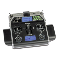
"Controls" include all operating elements on the trans-
mitter, which are directly activated by the pilot, that
impose an effect on servos, speed controllers etc.
connected to the receiver. This includes:
• both sticks for control functions 1 through 4,
whereby these four functions can be freely
swapped around for both model types ("winged
aircraft" and "helicopters") by way of software
"Mode" settings, e. g. throttle left or right. The
stick
function for throttle/airbrake control is often
also
referred to as the C1 control (channel 1).
• both proportional controls located on the transmit-
ter's sides, which are, for example, given the des-
ignations Lv1 (right-side "rotary slider") and Lv2
(left-side "rotary slider") in the »Control adjust«
menu, page 118 and 122.
• the three proportional sliders in the middle console
designated Sl1 … 3, for example as shown in the
»Control adjust« menu, page 118 and 122,
• all five proportional rotary controls on the transmit-
ter's front side, which are, for example, given the
designations DR1 … 5 in the »Control adjust«
menu, page 118 and 122,
• the switches present, if they are assigned to a
control channel in the »Control adjust« menu.
The proportional operating elements produce a direct
effect on servos which is commensurate with the con-
trol's position whereas switch modules can only effect
a two or three increment change.
Just which of these controls and switches operate which
of the servos 5 … 16 (max.) is freely programmable.
Important notice:
Inputs 5 … 15 for helicopters and 5
… 16 for winged aircraft are
generally "free", i. e. not assigned, in
the transmitter's basic programming.
Function input
This is an imaginary point in the signal path and must
not be considered the same as the point on the circuit
board where the transmitter control is connected. The
choice of "Stick mode" and settings in the »Con-
trol adjust« menu have their effect "downstream" of
these imaginary connection points. Thus differences
between the physical control's number and the number
of the downstream control channel can indeed emerge.
Control channel
From the point at which a signal contains all control
information necessary for a particular servo – whether
directly from the physical control or indirectly by way
of a mixer – the term "control channel" is used.
(The control function “Aileron” in a surface model is
so divided, for example the model type “2AIL” in the
control channels left and right aileron. Analogously,
e. g. in the Heli type “3sv (2Roll)” the control function
splits left and right in the control channels aileron
servo.)
This signal is only yet to be influenced by settings
made in the menus »Servo adjustment« and
»Transmitter output« before it leaves the transmit-
ter's RF module.
Once it arrives at the receiver, this signal may still
be modified by settings made in the telemetry menu
before finally being applied as a control quantity for
the respective servo.
Mixer
The transmitter's software contains a variety of mixer
functions. These can be used to apply one control
function to multiple servos or, conversely, to apply
multiple control functions to a single servo. Please
look over the numerous mixer functions in the text
beginning on page 171 of this manual.
Switches
The four standard toggle switches, the two 3-way
switches and both push-button switches can also
be incorporated into control programming. However,
these switches are generally intended for switch-
ing program options, e. g. to start and stop timers,
to switch mixers on and off, or as a teacher/pupil
switchover, etc. Each of these switches can be as-
signed any number of functions.
Appropriate examples are detailed in the manual.
Control switches
Since it is very practical to have some functions auto-
matically switched on or off for a certain control's po-
sition (e. g. switch on/off of a stopwatch for acquisition
of model run time, automatic extension of spoilers
and other possibilities), eight control switches have
been integrated into
mc-32 HoTT software.
These software switches, designated "C1 … C8", are
merely defined by virtue of their contact state along
 Loading...


