306
Programming examples - Parallel operating servos
Parallel operating servos
A second servo running in parallel is often required,
such as when brake flaps or spoilers installed in the
wings or the left and right elevator or a double fin
should be actuated by a servo or a large rudder flap
should be simultaneously controlled by two servos
due to high throw forces.
In principle, this task could also be solved by connect-
ing the servos together on the model side using V-
cable. However, the disadvantage here is that servos
combined in this manner can no longer be adjusted
individually and separately from the transmitter – thus
negating the potential for finely tuning respective
servos to one another with a computerized remote
control system. A similar situation is given for the so-
called "Channel mapping" feature of the »Telemetry«
menu. Here too there are certain limitations involved
when compared to the transmitter's adjustment pos-
sibilities.
The first example, therefore, describes the coupling of
two brake or spoiler servos, the second describes the
operation of two or more throttle servos and the third
describes the coupling of two elevator servos.
The "two rudder servos" example on the next page
describes the coupling of two rudder servos, whereas
Variant 1 is preferable for applications of this type
because the use of a cross-mixer« is quicker and
easier to program. In contrast, the second variant,
also described on the next page, additionally permits
asymmetric and/or non-linear curves through use of
the »Free mixer« menu.
Two brake or spoiler servos
In a situation where there is one installed servo for
operation of brake flaps and/or spoilers in each wing
half then the pre-set linear control characteristics for
the »Channel 1 curve« menu should remain un-
changed.
Then connect one of the two servos to Output 1, pro-
vided for this purpose by standard, and the second to
an arbitrary free receiver connection
5 … 16, such as Output "8". Subsequently switch
to the menu …
»Control adjust« (page 118)
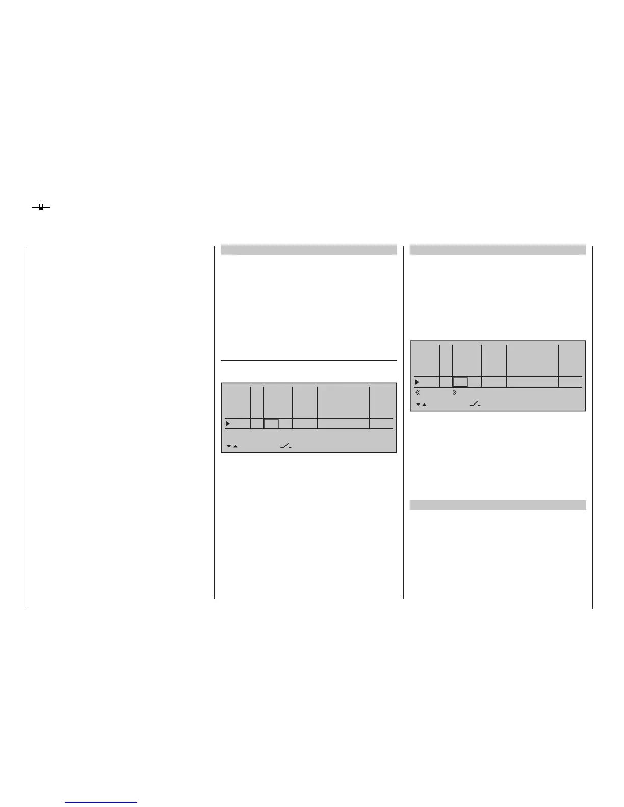
… and, using the selection keys, assign "Control 1" in
the Input 8 line :
0%
+100%I5
I6
I7
I8
Ty p
SEL
+100%
0.0 0.0
– travel + –time+
0%
+100%
+100%
0.0 0.0
0%
+100%
+100%
0.0 0.0
0%
+100%
+100%
0.0 0.0
GL
GL
GL
fr ---
fr
fr
Cn1
---
---
---
offset
GL
Normal
Since the spoiler on Output 1 can normally only be
operated on a flight-phase independent basis, it is
strongly recommended that the "Typ" column for the
input used is left at its "GL" default setting.
Also the remaining values should be left at their
default settings. If necessary, carry out the required
servo travel adjustments in the »Servo adjustment«
menu (page 112). There you can also adjust the travel
of servo 1 and 8 to one another, if necessary.
Multiple-motor aircraft
As described above, a model can also be operated
with two or more motors.
The first throttle servo and/or the first motor control is
connected as usual to (receiver) Output 1 and each
additional throttle servo and/or each additional motor
control is connected to a free (receiver) Output 6 …
16. The inputs of respective assigned control chan-
nels are then each assigned to Control 1; for exam-
ple:
0%
+100%I9
I10
I11
I12
Ty p
SEL
+100%
0.0 0.0
– travel + –time+
0%
+100%
+100%
0.0 0.0
0%
+100%
+100%
0.0 0.0
0%
+100%
+100%
0.0 0.0
GL
GL
GL
---
Cn1
---
---
---
offset
GL
Normal
Cn1
Cn1
Cn1
Since the motor control unit should be available
regardless of a currently active flight phase, make
sure to leave the standard default “GL” (“global”) in
the “Type” column.
The remaining values should be left at the default
settings. If you need to adjust servo travels, it is better
to use the »Servo adjustment« menu (page 112),
where you can adjust the settings as required without
having to switch menus.
Two elevator servos
Two elevator servos should be switched in parallel.
According to the receiver assignment plan, see page
65, the receiver output 8 is intended for the connec-
tion of the second elevator servo.