307
Programming examples - Parallel operating servos
This would be taken into account on the software side
in the pre-configuration of a corresponding mixer. You
can find this in the …
"Model type" (page 104)
In this menu, switch to the “Tail type” line using the
selection keys, activate the value field with a brief tap
on the centre SET key of the right key pad then select
the entry "2ELSv3+8":
Tail type
Motor on C1
none
Aileron/camber flaps
1 QR
M O D E L T Y P E
Brake Offset Input 1+100%
SEL
2 EL Sv 3+8
Then do the fine-tuning for travel of the two servos
"in the now familiar manner" in the »Servo adjust-
ment« menu.
Two rudders
We want to switch two rudders "in parallel". The sec-
ond rudder is located at the free receiver output 8.
Variant 1
The basis of this variant, as already mentioned the on
page 222, for the “normal” installation of the servos in
the fuselage and their connection to the rudder. That
is, both servos are parallel to each other vertically or
horizontally mounted in the fuselage, and both rud-
ders are either externally or internally connected in
the same direction of rotation to the servo arm.
In the following menu…
»Dual mixer« (page 222)
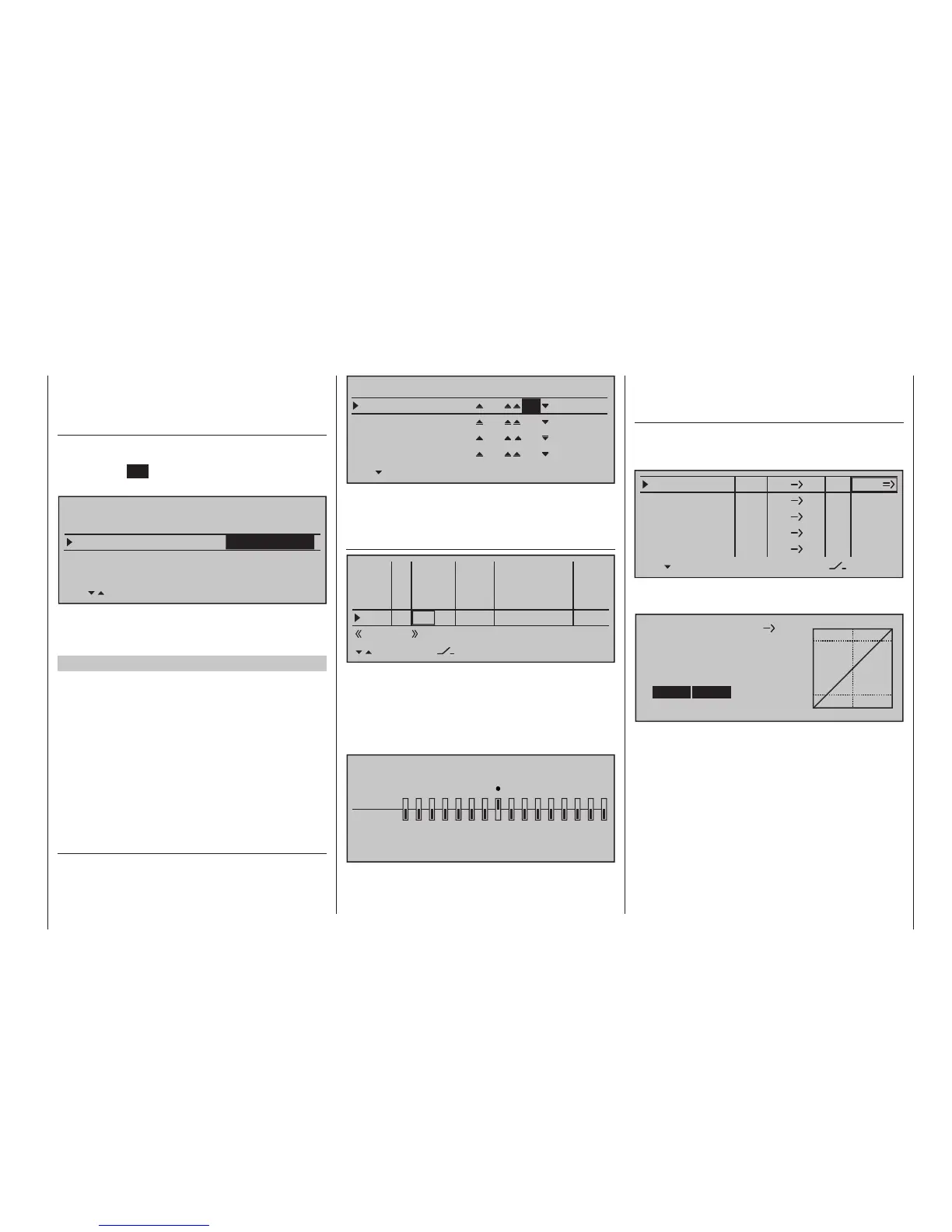
… select one of the dual-mixers and enter "8" and
"RU" in its left and centre value fields, as shown in the
figure:
Diff.
DUAL MIXER
Mixer 1
Mixer 2
8
RU
Mixer 3
Mixer 4
??
??
??
??
??
??
0%
0%
0%
0%
The same deflection " ", which would take place
through "Input 8" must not have an effect here. There-
fore, you should make absolutely sure in the …
»Control adjust« (page 118)
0%
+100%I5
I6
I7
I8
Ty p
SEL
+100%
0.0 0.0
– travel + –time+
0%
+100%
+100%
0.0 0.0
0%
+100%
+100%
0.0 0.0
0%
+100%
+100%
0.0 0.0
GL
GL
GL
fr ---
fr
fr
fr
---
---
---
offset
GL
Normal
… menu, that "Input 8" "GL(obal)" is set to "free" so
the control function is separate from the control chan-
nel over all flight phases.
Alternatively, Input 8 can be set to "no control" in the
»Mix only channel« menu on a ight-phase inde-
pendent basis by setting Channel 8 to "MIXonly".
MIX ONLY CHANNEL
MIXonly
normal
1
2
3
4
5
6
7 8 9 10 11 12 13 14 15 16
Variant 2
This variant uses the …
»Free mixers« (beginning page 209)
… menu to set a "Tr RU 8". In the "Type" column,
select the setting "Tr" so that the rudder trimming af-
fects both rudder servos:
8
LinearMIX 1
type
RU
from – Begr. +
??
??
??
??
??
??
––––
LinearMIX 2
LinearMIX 3
LinearMIX 4
LinearMIX 5
to
Adjust
––––
––––
??
??
––––
Tr
Afterwards, switch to the graphic screen and set a
symmetric mix of +100 %.
RU
Mix input Offset
8
Linear MIX 1
SYM ASY
STO
0%
SET
+100%
+100%
Here too, "Input 8" should also be programmed – if
applicable, for all flight phases – to "free" by way of the
»Control adjust« menu. However, control function
"8" can be separated from control channel "8" more
easily in the flight-phase independent »Mix only
channel« menu, page 221: