154
Program description - Phase settings | Winged models
Phase settings
Setting up flight phases
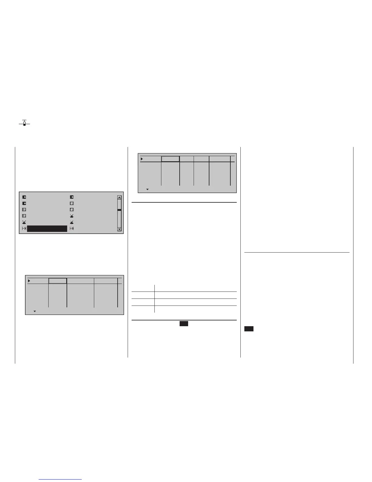
• Motor on C1 "Throttle min front/rear"
Phase 1
Phase 2
Phase 3
Phase 4
Phase 5
Name Timer
Sw. time
Motor
yes
0.1s
yes
0.1s
yes
0.1s
yes
0.1s
yes
0.1s
–
–
–
–
Setting up ight phases
When you set up flight phases for fixed-wing aircraft
models, you start with this menu. You assign individu-
al phases a name and also assign a period of time for
a (soft) transition into each phase. Note that – depend-
ing on your model and your settings – switch times
much longer than the default 0.1 s have proven use-
ful. You can also set up several phases with names
and transition times even if you don't currently have
a use for them, since the decision as to which of the
"occupied" phases you activate is made only on the
»Phase assignment« menu (page 160) when setting
"phase switches".
Whether or not one of the phases 1 … 8 currently has
an assigned switch and the state of the switch can be
seen in the "status" column at the far right.
Symbol Meaning
– No switch assigned
+ Phase can be accessed via switch
Indicates the phase currently active
"Name" column
Briefly tap on the centre SET key of the right touch
pad then assign the needed phases (phase 1 up to
maximum of 8 phases) by picking their names from
the selection list with the selection keys of the left or
right touch pad.
Within one model memory, the
mc-32 HoTT lets
you program up to 8 discrete groups of settings for
various conditions met during the flight.
The grouped settings are typically termed “flight phas-
es” and are programmed in the corresponding menus.
Use the selection keys of the left or right touch pad
to scroll to the »Phase settings« menu option in the
multi-function menu:
Servo adjustment
Stick mode
Control adjust
Dual Rate / Expo
Channel 1 curve
Switch display
Base setup model
Model type
Control switch
Logical switch
Phase settings
Phase assignment
Depending on the setting "Throttle min. forward/back"
or "None" in the "Motor on C1" line of the »Mod-
el type« menu (see page 104), calling up the »Phase
settings« menu option will cause the transmitter's
display to look like one of the two variants shown
below …
• Motor on C1 "none"
Phase 1
Phase 2
Phase 3
Phase 4
Phase 5
0.1s
0.1s
0.1s
0.1s
0.1s
Name
Fl.ph.Tim Sw. time
–
–
–
–
In addition to this standard pool of names, the »Gen-
eral basic settings« menu, page 280, permits up to
10 names of personal preference to be defined.
The order in which phases 1 to max. 8 are assigned is
entirely irrelevant and you can leave gaps as you wish.
Nonetheless, you should always start with "Phase 1",
the "Normal phase", which is always active if …
• … no phase switch is set in the »Phase assign-
ment« menu or if
• no phase has been assigned to specific combina-
tions of switches.
The definition of the phase name "Normal" could
therefore be a useful one to adopt for "Phase 1".
The names themselves have absolutely no technical
significance for programming; their only purpose is to
help you to identify which phase is active at any time
and are thus displayed in all flight phase-dependent
menus and also on the transmitter's basic display.
Column "Fl.ph.Tim" or "Timer"
In addition to the standard timers on the basic screen
display, other timers are also available whose settings
are configured in the »Flight phase timers« menu,
page 156.
Clk 1, Clk 2, Clk 3, Lap, Time1, Time2
The flight phase timers "Clk 1 … 3" plus "Time1" and
"Time2" run only in the flight phase to which they
have been assigned in this menu. During other flight
phases they are stopped (and hidden) and the as-
signed stop/start switch then has no effect.
The lap counter, once started, continues to run
through changes of phase, however, although it can
be stopped during any flight phase via the centre
ESC key of the left touch pad.