155
Program description - Phase settings | Winged models
While you can obviously record lap times using "Lap"
and a switch, the two timers "Time1" and "Time2"
have the following meaning:
Time 1
This timer will only measure time during which
the switch or control switch assigned in the "Lap
time/Tim tab" line of the »Flight phase timers«
menu, page 160, is "closed". The frequency at
which the switch is activated is shown on the
basic display. This counter field is highlighted
as soon as the switch for the "Time1" timer is
"opened", i. e. the timer is stopped:
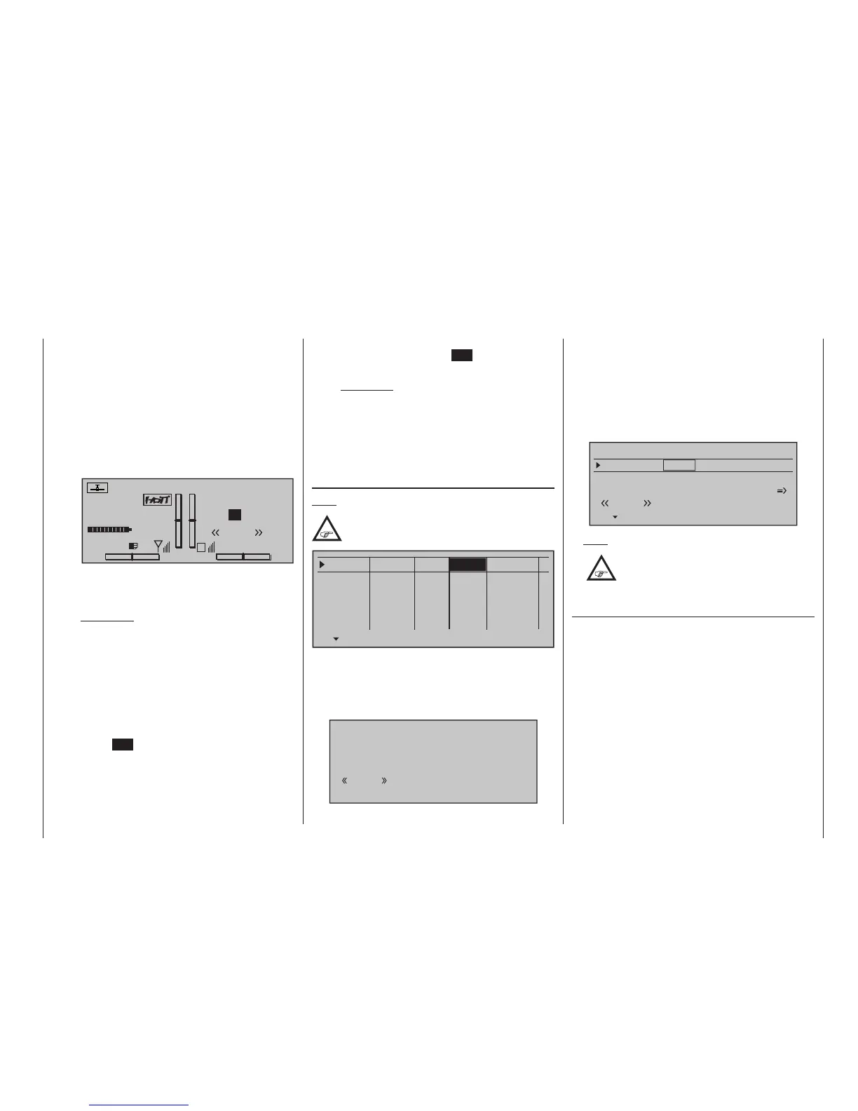
#01
0:00h
Stop watch
Flight tim
K78
0:00.0
4.1V
0:00.0
00
0
0
0:00h
M
V
Graubele
H-J Sandbrunner
Normal
Lap
00
0.0s
RX VOLT:4.9V
When necessary, the selection keys can be
used to access and read the sequence of
switching times.
Application:
Measurement of e. g. motor switch-on times, if
the same switch also actuates the motor.
Time 2
This timer stores both the "off" and the "on"
periods for the associated switch, i. e. every
switch actuation in either direction will cause a
record to be written for the timer, the timer will
be reset then starts increasing by "1" again as
time passes.
Each time count can be suspended with the
centre ESC key of the right touch pad, without
actuating the switch itself. Activating the switch,
in turn, increments the counter by 1 and re-
starts the "Time 2" timer.
In order to read out the time memory with the
selection keys, the "Time 2" timer must first be
suspended by using the ESC key of the right
touch pad.
Application:
In addition to the motor runtimes, for example,
the unpowered glide times between these
could also be recorded.
A simultaneous tap on the or keys of the
right touch pad (CLEAR) will reset suspended timers
shown in the basic display.
"Motor" column
Note:
This column is only available if "forward/back"
is present in the "Motor on C1" line of the
»Model type« menu, page 104.
Phase 1
Phase 2
Phase 3
Phase 4
Phase 5
Name Timer
Sw. time
Motor
0.1s
yes
0.1s
yes
0.1s
yes
0.1s
yes
0.1s
–
–
–
–
Normal
Launch
Dist.
yes
• "yes"
The motor connected to receiver output 1 will be
controlled by the C1 stick (throttle/brake stick).
The brake system to be set up on the »Wing mix-
ers« menu is deactivated:
BRAKE SETTINGS
Normal
off
• “no”
The motor connected to receiver output 1 is de-
coupled from the C1 stick (throttle/brake stick) and
is held in its OFF position – as specified by the set-
ting "Throttle min. forward / back" – automatically.
The brake system to be set up in the »Wing mix-
ers« menu is activated and is actuated by the C1
stick.
Elevator curve
BRAKE SETTINGS
Normal
Crow
AILE
0%
WK2
0%
WK
0%
Diff.- reduct
Note:
The settings available depend on the
number of control surface servos selected
on the line "Ailerons/Camber-changing
aps in the »Model type« menu.
"Sw. time" column
When you switch between flight phases, it is advis-
able to use this column to program a switch time
for a "soft" transition INTO (!) the respective phase.
Accordingly, there is also an option for specifying a
different time for the switchover from any phase to, for
example, Phase 3 than for a switchover to Phase 1.
Use the selection key of the left or right touch pad
to move the marker frame to the right beyond the
column labelled "Timer" and, if applicable, also the
column labelled "Motor".