84
Program description - Base setup models | Winged models
To be on the safe side, keep them at
least one meter apart. Otherwise there
is a risk of a faulty connection to the
return channel and malfunctions will
result.
• Pay close attention to the correct power
supply of the receiving system. Too low
supply voltage while responding the
LEDs of the receiver as described below
on your Binding effort, yet there is no
proper HoTT Synchronization.
• When binding additional receivers, note
that any other – switched on – receivers
already bound to the transmitter will
fall into Fail safe mode during the
transmitter-side “binding” period.
“Binding” multiple receivers per model
Multiple receivers per model can be bound if desired,
whereby
mc-32 HoTT programs offer the potential
for managing up to two receivers directly and for di-
viding up the transmitter’s 16 control channels (max)
in any arrangement among these receivers under
menu control. Refer to additional details further down
in this section. First bind the receivers individually as
described below.
When the system is actually in use, the
only receiver which creates a telemetry
link to the transmitter is either the last
receiver to be bound, or the receiver which you
selected in the “TEL.RCV.” line of the »Telem-
etry« menu, for example:
TELEMETRY
SETTING & DATAVIEW
SENSOR SELECT
RF STATUS VIEW
VOICE TRIGGER
TELEMETRY RCV
BIND. 1
Any telemetry sensors which may be built into the
model should therefore be connected to this receiver
because the transmitter only receives and evaluates
data from the return channel of the receiver activated on
this line. The second, and all other receivers, operate in
parallel but are fully independent in slave mode.
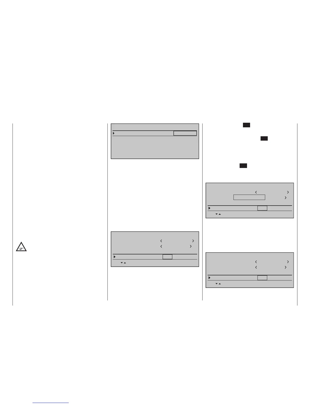
"Binding" transmitter and receiver
Use the selection keys of the left or right touch
pad to move into the "Module" line. The marker frame
will be positioned by default to the column for the next
free binding channel. In the example shown in the
figure below, the marker frame is positioned above the
column label "BD2" because the binding channel in the
column labeled "BD1" is already in use by default for
the receiver which was delivered with the set.
Model name
Stick mode
1
n/a
BASIC SETTING,MODEL
Info
n/a
n/a
Module
bind
HoTT
Graubele
1234g/111111
SEL
BD1
BD2
BD3
BD4
If not already off, now switch the receiver on.
• Receiver GR-32 DUAL
The red LED on the GR-32 HoTT receiver will
blink.
Press and hold the SET button on the receiver
while the LED continues to blink red for about
3 seconds then, after about another 3 seconds,
begins to blink red/green. The SET button on the
receiver can now be released. As long as this LED
blinks red/green, the receiver is in bind mode.
Now, within this 3 second period, start the so-
called "receiver binding" process for the receiver
to the currently active model memory with a brief
tap on the centre SET key of the right touch pad.
At this time, the screen's display will blend in a
message window for the duration of the "binding"
process.
Model name
Stick mode
1
n/a
BASIC SETTING,MODEL
Info
n/a
n/a
Module
bind
HoTT
Graubele
1234g/111111
SEL
BD1
BD2
BD3
BD4
FINDING...
If the receiver's LED, again blinking red, changes
within about 10 seconds to continuous illumination
in green, the binding process has been success-
fully completed. Your model-memory to receiver
combination is now operationally ready. At this
time the screen will now display " bind " (bound)
instead of "n/a" (not attached).
Model name
Stick mode
1
bind
BASIC SETTING,MODEL
Info
n/a
n/a
Module
bind
HoTT
Graubele
1234g/111111
SEL
BD1
BD2
BD3
BD4