88
Program description - Base setup models | Winged models
• You would like to control the rudder of a large
model with two or more servos.
Assign each of the appropriate outputs (servo
connections) to one and the same input (control
channel). In this case, the default rudder channel
(4), see gure bottom right.
Notes:
•
The maximum number of lines (outputs)
available corresponds to the maximum
number of servos which can be connected
to the receiver in question.
• If you see the warning …
CAN‘T
RECEIVE
DATA
OK
… then there is no bound receiver within range.
If the case may be, switch the RF module or/and
your receiving system on.
• With the »Tx. output swap« option, available
on the
mc-32 transmitter, see page 234, the
transmitter’s control functions can be interchanged
in any way; it is also possible to assign multiple
outputs to one and the same control function. In
the interests of clarity however we strongly advise
that you use only one of these two options.
Channel assignment on other receivers
As already mentioned, the "Rcv Ch map" menu op-
tion can be used to freely distribute the
mc-32
HoTT transmitter's 16 control channels across up
to four receivers, whereby the numbering of outputs
(servo connections) as well as the maximum num-
ber of available lines (outputs) will correspond to the
maximum number of servo connections available on
the given receiver.
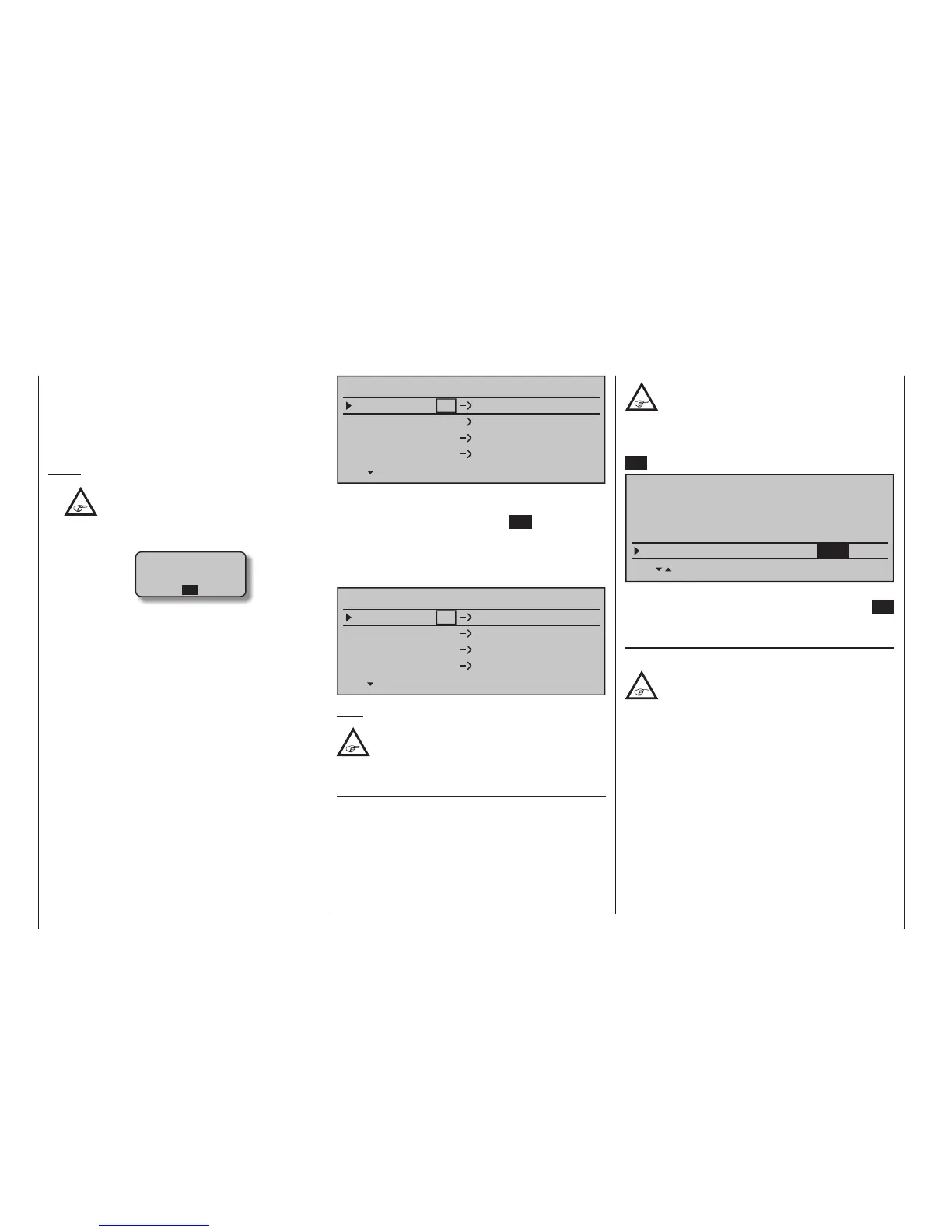
RECEIVER CHANNEL MAP BIND2
Rx Input Ch 16
Rx Input Ch 16
Rx Input Ch 16
Rx Input Ch 16
Rx Output Ch 1
Rx Output Ch 2
Rx Output Ch 3
Rx Output Ch 4
After selection of the desired output with the selection
keys of the left or right touch pad, the respective input
fi eld will be framed. Tap the centre SET key of the
right touch pad. The current setting will be displayed
in inverse video. Now select the desired input chan-
nel with the selection keys of the right touch pad. For
example, suitable to the above rudder example.
RECEIVER CHANNEL MAP BIND2
Rx Input Ch 4
Rx Input Ch 4
Rx Input Ch 4
Rx Input Ch 4
Rx Output Ch 1
Rx Output Ch 2
Rx Output Ch 3
Rx Output Ch 4
Note:
The number of lines available in the list
(outputs) corresponds to the maximum
number of servos which can be attached to
the given receiver.
RF transmit
This menu line provides an option for manually
switching the transmitter's RF transmission on and
off to specifi c models while the transmitter is in op-
eration. For example, to save power while a model is
being programmed.
If this line option was set to OFF, it will be
canceled (i. e. set to ON) the next time the
transmitter is switched on.
If necessary, use the selection keys of the left
or right touch pad to move into the "RF transmit" line
then activate the option with a brief tap on the centre
SET button of the right touch pad.
Stick mode
Module
1
bind
bind
n/a
n/a
HoTT
SET SET SEL SET
Rcv Ch Map R16 R08
n/a
n/a
RF transmit on
BASIC SETTING,MODEL
The right selection keys can now be used to choose
between OFF and ON. Another tap on the centre SET
key of the right touch pad will conclude the entry.
Range test
Note:
This menu line is when “EXT. PPM “in the
line” module hidden “.
The built-in range test reduces transmission power
to an extent that a functional test can be carried out
even within a distance of less than 100 m.
Perform a range test on the Graupner HoTT system ac-
cording to the following instructions. If necessary, have
someone assist you in carrying out the range test.
1. Preferably, the receiver already bound to the
transmitter should be installed into the model in its
intended position.
2. Switch remote control on and wait for the green
LED to light up on the receiver/s. Now servo
movements can be observed.