55
Receiver power supply
Receiver system
power supply
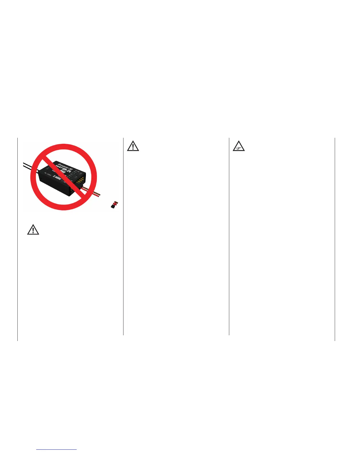
... but never so:
ATTENTION:
At the receiver, GR-32 “T” (telemetry) and
“S” (“Signal”) servos and other components
are connected horizontally only at the termi-
nals 13 to 16.
Under no circumstances may be connected across
the other terminals 1 to 12 components and espe
-
cially the receiver battery as shown demonstratively
in the figure above. The same applies to the termi-
nals 1 ... 6 of the receiver GR-12L. A plug in “cross”
over 2 to 3 terminals, immediately leads to a short
circuit of the receiver battery; the destruction of
possibly connected components and the immediate
loss of warranty claims.
The sequence in which servos are connected to the
receiver depends on the type of model. Follow the
con-
nection layouts provided for this on pages 65 and 69.
Also observe the safety notices provided on pages 4 …
10.
In order to prevent uncontrolled movements
of servos connected to the receiver during
startup
always rst switch on the transmitter
and then the receiver
and when finished with operation
rst switch off the receiver
and then the transmitter.
When programming the transmitter, be sure that elec-
tric motors cannot start running without control or that
a combustion motor equipped with automatic starting
cannot start up unintentionally. To be safe, disconnect
the receiver's drive battery or, in the case of a com-
bustion motor, disconnect the fuel supply.
Among other aspects, the safe operation of a
model depends on a reliable power supply. In
the event that, despite smooth operating rods,
fully charged battery, battery leads with adequate
cross-section, minimum contact resistances at con-
nectors, etc., the transmitter indicates repeated re-
ceiver voltage collapses or is receiver voltage is
generally too low; please give attention to the follow-
ing notices:
Give primary attention to fully charged batteries when
model operation is to be started. Be sure that the
contact surfaces of connectors and switches really
are low resistance. If necessary, measure the voltage
drop across installed switch cables when they are
under load because even new heavy-duty switches
can cause a voltage drop of up to 0.2 V. This value
can increase in contacts by factors as a consequence
of aging and oxidation. The constant vibrations and
jarring also takes its toll on contacts to produce a
creeping increase of contact resistance.
Servos present another possible problem source.
Even rather small servos like a Graupner/JR DS-281
can draw up to 0.75 A of current when it is blocks un-
der load. Just four of these servos in a “foam” model
can therefore load down the on-board power supply
by as much as 3 A …
A further factor is that 2.4 GHz receivers generally
pass control signals to servos at a higher rate than
with comparable receivers used in earlier frequency
ranges. This equates to shorter “off” periods, which
also has an effect on the power consumption of the
receiving system. The current drain of many of today’s
digital servos is also higher, reflected by their greatly
improved ability to hold the prescribed position be-
tween control signals.Therefore you should choose a
power supply which will not break down under greater
loads but rather always deliver sufficient voltage. To
“calculate” necessary battery capacity you should
always figure on at least 350 mAh for every analog