264
Program description - Channel sequencer
Important notices:
• The sequence shown is only for demonstration
purposes and is not at all representative of a real
sequence of servo movements.
• The settings made in the “POS” value eld
replace the otherwise “conventional” transmitter
control signal. Therefore it is necessary, before
programming such a sequence, to check in the
»Servo display« menu to make sure none
of the channels planned for the sequence are
actuated by any other transmitter operating
element. If this were to be the case, it could
lead to unpredictable excursions in the motion
sequence. Use the options of the »Only MIX
channel« menu (page 221).
• The settings made in the »Servo adjustment«
and »Tx. output swap« menus are not affected
by settings in this menu. When preparing and
creating a sequence, be absolutely sure the
servos do not collide mechanically. If necessary,
use the “Travel limit” option in the »Servo
adjustment« menu (page 112).
Multichannel
Channel multiplier for special functions
The
mc-32 HoTT transmitter has an integrated
multi-function channel built into the transmitter's soft-
ware. This facility permits up to two control channels to
be used for up to four or eight special functions. Every
available switch (including the so-called expansion
switches, see page 60) or transmitter control can be
assigned on the transmitter side.
On the receiver side, the following modules are avail-
able as accessories, whereby at one time a maximum
of two modules can be operated via the »Multi-chan-
nel« menu.
NAUTIC-Expert, switching module, No. 4159
The NAUTIC-Expert switching module expands a
servo's functionality to 16 switched functions. By
appropriately wiring the connecting cable, loads can
either be operated from a common power supply or
also separately by multiple power sources.
NAUTIC-Multi-Prop mini-decoder No. 4142.N
The 1/4 C-NAUTIC-Multi-Prop mini-decoder expands
a proportional function to four proportional functions.
Light module No. 2381
A module for switching the light signals of rail, road
and airborne vehicles with true authenticity.
Sound switch for vehicle models No. 2382.F
start, stop and supplementary sounds as well as typi-
cal vehicle signals
Sound switch for ship models No. 2382.S
start, stop and supplementary sounds as well as typi-
cal ship signals
Further information can be found in Internet at
www.graupner.de. Use the search mask by entering
the respective No. Alternatively, contact or visit your
local dealer.
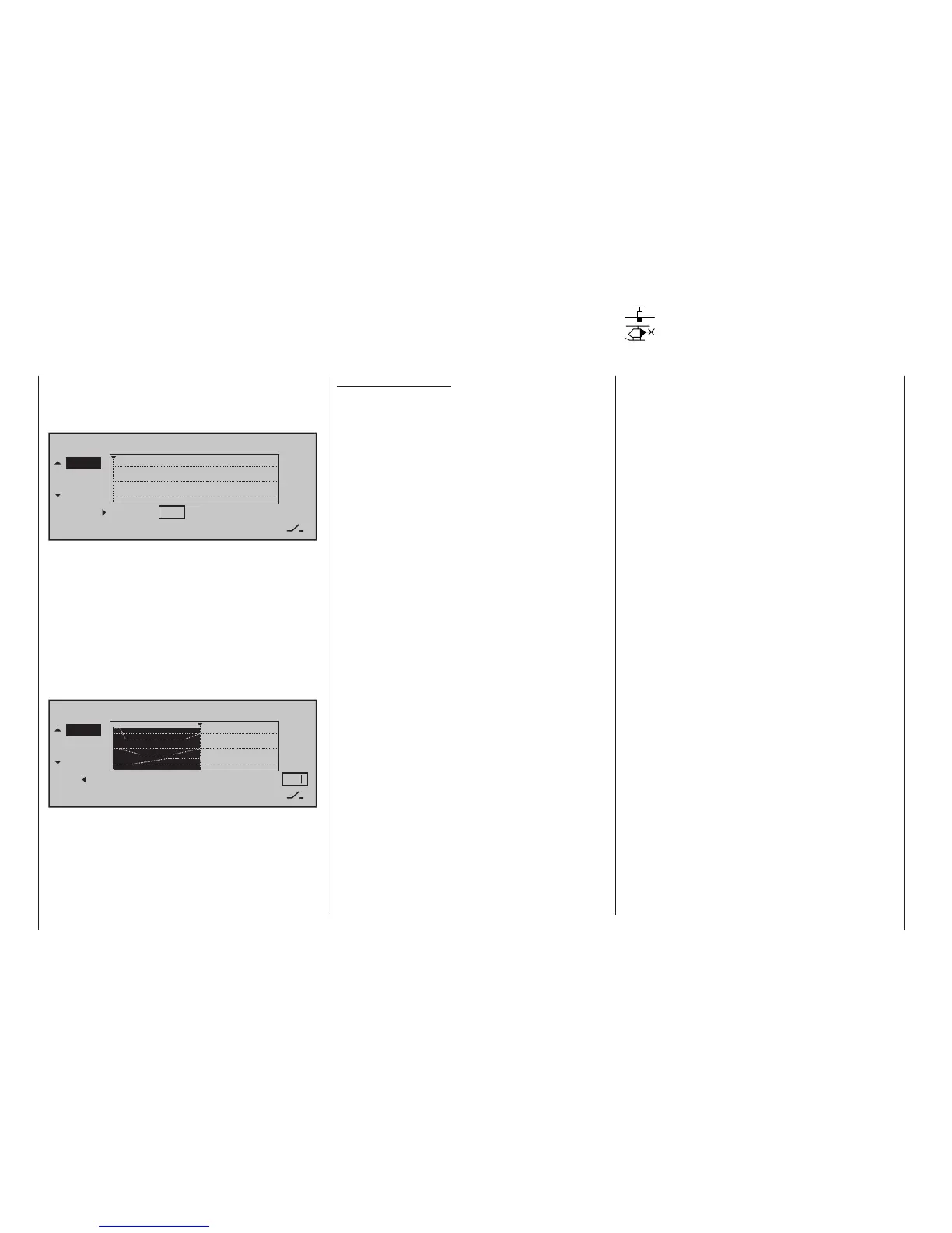
A simultaneous tap on the or keys of the right
touch pad (CLEAR) will reset the inverse video value
displayed if the TIME field back to "blank" and erase
the current sequence, in this example only Step "1".
Channel sequencer
TIME
STEP
11
12
0
POS
–––
10
+90%
0.0s
Step 2 …
Repeat the previously described procedure for every
other step to be defined until the servos have reached
their terminal positions.
Switch assignment
In conclusion, assign the sequence of events created
to a switch (as described on page 0 in the section
"Assigning transmitter controls, switches and control
switches") with which the servos can be switched
between their initial and terminal positions.
Channel sequencer
TIME
STEP
11
12
8
POS
10
0%
0.0s
2
As soon as this switch is closed, the servos' se-
quence of movements can be followed in the graphic.
The servo curves will be shown in inverse video
according to the preset time windows. All movements
will sequence in reverse when the switch is opened
again.