19
General operating notices
Charging with automatic chargers
To achieve quicker recharging of the single cell LiIo
battery, Graupner automatic chargers can also be
used. The table below shows a selection of these
chargers.
Recommended chargers (accessory)
Order
No. Designation
Input voltage 220 V
Input voltage 12 V
suitable for
battery types
integr. balancer
NiCd
NiMH
LiPo/LiIo
lead battery
6411
Ultramat 8 x x x x x
6463
Ultramat 12 plus x x x x x x
6464
Ultramat 14 plus x x x x x x x
6466
Ultra Trio plus 14 x x x x x x x
6468
Ultramat 16S x x x x x x x
6469
Ultra Trio Plus 16 x x x x x x
6470
Ultramat 18 x x x x x x x
6475
Ultra Duo Plus 45 x x x x x x x
6478
Ultra Duo Plus 60 x x x x x x x
6480
Ultra Duo Plus 80 x x x x x x x
Charger cable, No. 3022 is additionally needed for the transmitter
and charger cable, No. 3021 is additionally
needed for the receiver.
Other charger units and details about the listed chargers can
be found in the Graupner RC main catalog or in Internet at
www.graupner.de.
The charger socket is equipped standard with a
diode to protect against reversed polarity. Original
Graupner automatic chargers also detect battery
voltage polarity.
Observe the confi guration notices for the charger
used.
First connect the charger cable's banana
plugs to the charger and only then con-
nect the cable's other end into the charg-
ing jack on the transmitter. Never allow the bare
ends of the banana plugs to come into contact
with one another when the other end of the cable
is plugged into the transmitter.
Charging current may not exceed 1.5 A as other-
wise the diode, and perhaps other components,
could be damaged. If necessary, limit the current
at the charger.
mc-32 HoTT charging jack polarity
The charger cables on the market from other manu-
facturers often have different polarities. Therefore use
only an original Graupner charger cable, No. 3022.
Removing the transmitter's battery
To remove the transmitter's battery, fi rst unlatch the
cover of the battery compartment on the rear side of
the transmitter housing then remove the cover.
Take out the transmitter's battery then disconnect the
transmitter battery's connector by carefully pulling on
the supply line cable.
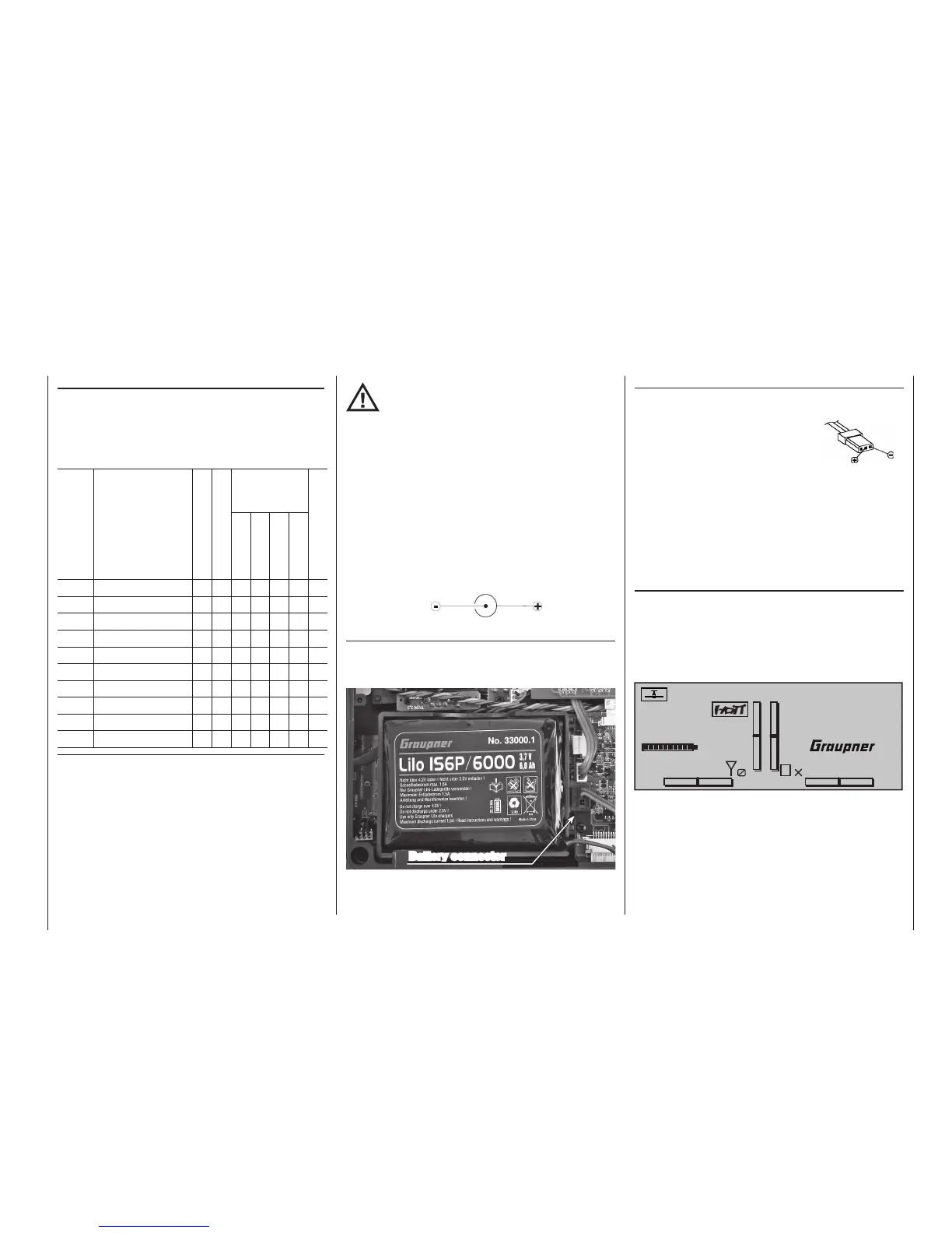
Inserting the transmitter's battery
The battery connector is protected against a reverse
polarity connection by two slanted edges, see illustra-
tion. When correctly plugged in, the
unconnected pin of the connector
is at the bottom, as shown in the
illustration. The plus pole (red lead)
is in the middle and the minus pole
(brown or black lead) is toward the
antenna side.
Never try to force the connector
onto its circuit-board socket.
Place the battery into its compartment and close the
transmitter's cover.
Battery operation timer at the bottom left of the screen
This timer shows the transmitter's cumulative operating
time since the transmitter's battery was last charged.
This timer is automatically reset to "0:00" when the
transmitter is switched on and its battery voltage is
signifi cantly higher than when the transmitter was last
used, e. g. because the battery was charged.
#01
0:00h
Stop watch
Flight tim
K78
0:00.0
4.1V
0:00.0
00
0
0
0:00h
M
V
Transmitter
connector polarity
Battery connector