303
Programming examples - Winged models
C1 stick switchable between E-motor and spoiler
Example 5
If, contrary to the assumptions of the preceding Ex-
ample 4, the model has additional spoilers or only
spoilers, they can be incorporated into the control of
the model by means of the following programming.
Do this by programming the menus »Model type«,
»Phase settings« and »Phase assignment« in the
same manner as described under Example 4. The
settings described there in the "Brake settings" sub-
menu of the »Wing mixers« menu are only then rel-
evant if an additional crow system is to be employed
in parallel with the spoilers.
With the settings described under Example 4, the
control of the E-motor and, if applicable, that of a
crow system will function as usual. Only the control
of a spoiler connected to Output 8, for example, must
additionally be programmed. For this purpose, switch
to the menu …
»Control adjust« (page 118)
… and switch into the «normal» flight phase.
Now use the selection keys to switch to the left into
the "Typ" column to set the parameter in this line, e. g.
"I8" from "GL(obal)" to "PH(ase)", so that the settings
too follow become effective on a flight-phase specific
basis.
0%
+100%I5
I6
I7
I8
Ty p
+100%
0.0 0.0
– travel + –time+
0%
+100%
+100%
0.0 0.0
0%
+100%
+100%
0.0 0.0
0%
+100%
+100%
0.0 0.0
GL
GL
fr ---
fr
fr
---
---
offset
GL
Normal
PH
SEL
fr ---
Afterward, switch to the "Offset" column and, following
activation of the value field with a brief tap on the SET
key of the right touch pad, change the offset value for
this Input 8 value field now displayed in inverse video
until the spoilers are again "retracted", e. g.:
0%
+100%I5
I6
I7
I8
Ty p
+100%
0.0 0.0
– travel + –time+
0%
+100%
+100%
0.0 0.0
0%
+100%
+100%
0.0 0.0
-95%
+100%
+100%
0.0 0.0
GL
GL
fr ---
fr
fr
---
---
offset
GL
Normal
PH
SEL
fr ---
Confirm this setting with a brief tap on the centre ESC
key of the left key pad or the centre SET key of the
right touch pad then switch to the left into the column
above SEL. Now switch to the flight phase «Land-
ing» then briefly tap on the centre SET key of the
right touch pad. The display shows the window …
0%
+100%I5
I6
I7
I8
Ty p
+100%
0.0 0.0
– travel + –time+
0%
+100%
+100%
0.0 0.0
0%
+100%
+100%
0.0 0.0
+100%
+100%
0.0 0.0
GL
GL
fr ---
fr
fr
---
---
offset
GL
Landing
PH
SEL
fr ---
0%
Move desired
control adj.
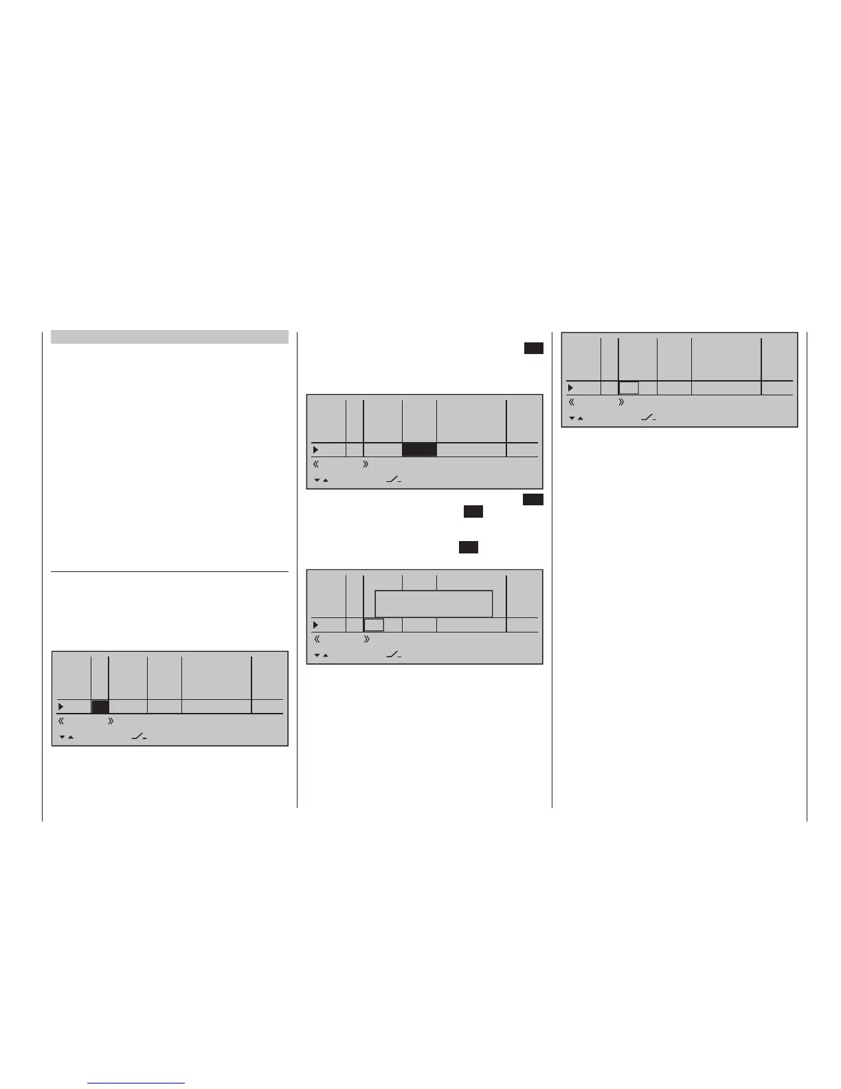
Now move the C1 stick. As soon as this is recog-
nized, "Cn1" will appear in the display instead of "fr":
0%
+100%I5
I6
I7
I8
Ty p
+100%
0.0 0.0
– travel + –time+
0%
+100%
+100%
0.0 0.0
0%
+100%
+100%
0.0 0.0
+100%
+100%
0.0 0.0
GL
GL
fr ---
fr
fr
---
---
offset
GL
Landing
PH
SEL
Cn1 ---
0%
Leave the offset value in this flight phase at "0 %". It
may be necessary to change the leading symbol of
the travel setting to reverse the control direction. Do
this by switching the travel setting from +100 % to
-100 % in the "travel" column.
Now we are practically finished. Check the program-
ming in the »Servo display« menu, which you can
reach from the base screen of the transmitter as well
as nearly every other menu position with a simulta-
neous tap on keys of the left touch pad. You will
discover that "Servo 1" (motor control) is controlled in
the "Normal" phase and in the "landing" phase only
the spoiler is controlled at "Servo 8" and, if applicable
the aileron and flap servos – just as we intended.