208
General notes on freely programmable mixers
The previous pages have described a wealth of
ready-to-use built-in coupling functions, in the context
of the two menus »Wing mixers« and »Helicopter
mixers«. The fundamental significance of mixers and
the principle by which they work are described on
page 171. The following section provides information
about the so-called "free mixers".
In addition to the pre-programmed mixers mentioned
above, the
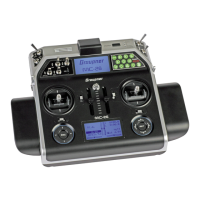
mc-32 HoTT also offers a number of
freely programmable mixers in every model memory
location, whose inputs, outputs and mixer ratios can
be defined to meet one's own requirements. These
include:
• 8 linear mixers, numbered 1 through 8
• 4 curve mixers, numbered 9 through 12
These 12 mixers are certainly adequate for most ap-
plications and are certainly sufficient when the po-
tential of the pre-programmed coupling functions are
utilized. In the »Mix active/phase« menu (see page
220), each of these 12 mixers can be activated or
deactivated separately for each flight phase.
For the "free mixers", the signal present at any con-
trol function (1 to 16) can be assigned as the input
signal or, for a so-called "switch channel" (see further
below), the signal from any switch can be utilized.
The signal that is present at the control channel and
passed to the mixer input is always influenced by its
own transmitter control and by any control charac-
teristic that may have been set, e. g. those specified
by the »Dual Rate / Expo«, »Channel 1 curve« and
»Control adjust« menus.
The mixer output acts on a control channel (1 to – de-
pending on receiver type – a maximum of 16) that can
also be assigned freely.
Before this channel routes the signal to the servo,
it can only still be influenced by the »Servo adjust-
ments« menu, i. e. by the servo reverse, neutral point
offset, servo travel and servo travel limit functions,
and possibly by »Tx. output swap«.
One control function (page 58) can be used for any
number of mix inputs simultaneously: if, for example,
several mixers are to be switched to act in parallel.
Conversely, it is possible for any number of mixers to
affect one and the same control channel (page 58).
Particularly in the latter case, however, it is very im-
portant to ensure that the servo concerned does not
strike its mechanical end-stops when several mixer
signals accumulate excessively. For safety's sake,
it may therefore be necessary to set an appropriate
travel limit in the »Servo adjustments« menu (page
112).
For more complex applications, mixers can be switched
in sequence. In this case, it is not the (transmitter) sig-
nal at the "output" of a control function which forms the
input signal of the "series-wired" mixer, but the (mixed)
signal "further back" at the "input" of a control channel.
The following description of the free mixers includes
several examples of this type.
In the software, a "free mixer" is always initially acti-
vated. Optionally the mixer can also be assigned to an
ON/OFF switch. Since there are so many functions to
which switches can be assigned, be careful to avoid
(undesired) multiple assignments to a single switch.
The two key mixer parameters are:
• … the mixer ratio, which defines the extent to
which the input signal acts on the output of the
control channel connected to the mixer output.
The mixer ratio for linear mixers can be set as
symmetrical or asymmetric.
Curve mixers can also be configured with up to
8 points to suit one's own application and even
implement extremely non-linear curves.
• … the neutral point of a mixer, which is also
referred to as the "offset".
The offset is that specific point along the
movement of a transmitter control (stick,
proportional control or switch) at which the
mixer no longer influences the control channel
connected to its output. Normally, the neutral
point is the centre point of the transmitter control.
However, the offset can also be set at any other
point along the control travel. Since there are no
restrictions on the design of the curve mixers,
setting a mixer neutral point only makes sense for
the 8 linear mixers.
Switch channel "S" as a mixer input
Occasionally, however, only a constant control sig-
nal is required at the mixer output, e. g. for a slightly
increased "up-elevator" trim when the aero-tow re-
lease is closed – fully independently of its normal trim
setting.
In this case a switch is assigned both to the aero-tow
release and the mixer; it is then used not only to open
and close the release, but also to pass the desired
trim signal to the elevator via the mixer ratio. To iden-
tify this special arrangement, this mixer input control
function in the program is designated "S" for "Switch
channel".
In addition, if the corresponding "target channel"
should now no longer be influenced by its "normal"
transmitter control, isolate the latter from the function
input of the affected control channel by way of the
»MIX-only channel« menu (page 221). Here too, for
clarification of this there is an example of the function
provided in the following menu description.
General notes on freely programmable mixers
 Loading...


