147
Program description - Control switches
Typical applications:
• On/Off switching of an on-board glow plug in
conjunction with the carburettor setting and/or
motor speed. (The glow plug heater switch for this
will be controlled by a transmitter-side mixer.)
• Switching a stopwatch on or off to measure the
simple running time of electric motors
• Automated switch-off of a combi "aileron rudder"
mixer when extending the airbrakes, e. g. so as to
match the bank attitude of the model to the ground
slope when landing on a ridge, without the direction
of ight also being affected by the rudder (if the
mixer were active).
• Lowering landing aps, adjusting elevator trim
and/or executing specic Dual Rate, Exponential
and Differential switchings when coming in to land,
as soon as the throttle stick is moved beyond the
switching point. If required, a control switch can be
overridden using a separately assigned switch in
the 5th column.
The
mc-32 HoTT program is equipped with a total
of eight so-called control switches ("C1" to "C8").
Accordingly, anywhere where switches can be as-
signed you have the option not only of using the 16
possible transmitter switches, but also of choosing
and assigning one of the "C1" … "C8" control switch-
es from the list of expanded switches – as described
in the section "Assigning transmitter controls, switch-
es and control switches" on page 60.
Furthermore, combining a control switch with an ad-
ditional switch (as described later) also permits more
complex switching permutations.
Basic procedure:
1. If no transmitter control is assigned, the
corresponding input field of the column labeled
SEL (second column from the left) will be empty.
2. Use the selection keys of the left or right touch
pad to select the line for the desired control switch
(1 to 8).
3. Briefly tap the centre SET key of the right touch pad.
4. Move your selected transmitter control.
The associated transmitter control number
appears in the input field of the column above the
left switch icon.
5. Use the selection keys on the left or right touch pad
to move to the right into the column labeled STO.
6. Move the transmitter control to the desired switching
point then briefly tap on the centre SET key of the
right touch pad to save the switching point.
7. Complete the remaining settings such as switching
direction, etc.
8. Exit from the menu with a tap on the centre ESC
key of the left touch pad.
Assigning a transmitter control to a control switch
Using the selection keys on the left or right touch
pad, select your chosen line (1 to 8). Following a final
tap on the centre SET key of the right touch pad to
activate the control assignment, the message shown
below will appear in the display:
SEL
0%
0%
0%
C1
C2
C3
–––
C4
CONTROL SWITCH
Geb. 1
0%
STO
–––
–––
–––
SEL
C1
C2
C3
C4
frei
free
free
frei
Move desired
control adj.
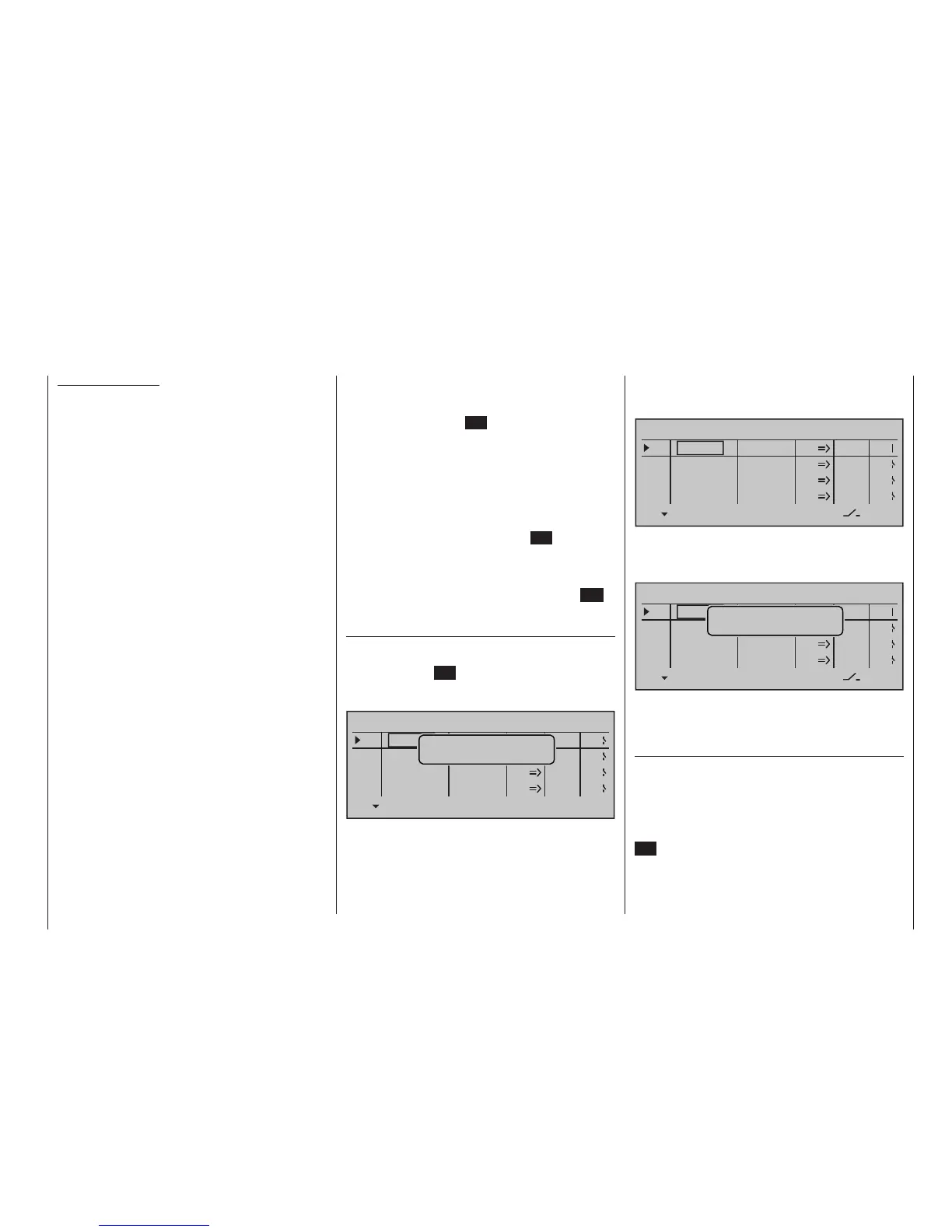
For example, the right-side proportional slider is now
to be assigned to control switch "C1", the default
throttle limiter for a helicopter model memory.
So just move this control in any direction. As soon
as this is detected, the control name appears on the
display:
SEL
0%
0%
0%
C1
C2
C3
–––
C4
CONTROL SWITCH
Lever1
free
0%
STO
–––
–––
–––
SEL
C1
C2
C3
C4
free
free
Resetting a control switch back to "free"
To reset a control switch back to "free", make sure the
display is as below …
SEL
0%
0%
0%
C1
C2
C3
–––
C4
CONTROL SWITCH
Lever1
free
0%
STO
–––
–––
–––
SEL
C1
C2
C3
C4
free
free
Move desired
control adj.
… then, with a brief simultaneous tap on the or
keys of the right touch pad (CLEAR), the entry
for a control will be erased.
Dening the switching point
Using the selection key of the left or right touch
pad to move the marker frame into the column la-
beled STO (store).
Move the selected transmitter control to the position
at which the switching point, i. e. the switch between
OFF/ON, should trigger and briefly tap the centre
SET key of the right touch pad. The current position is
displayed, for example "+85 %":