193
Program description - Helicopter mixer
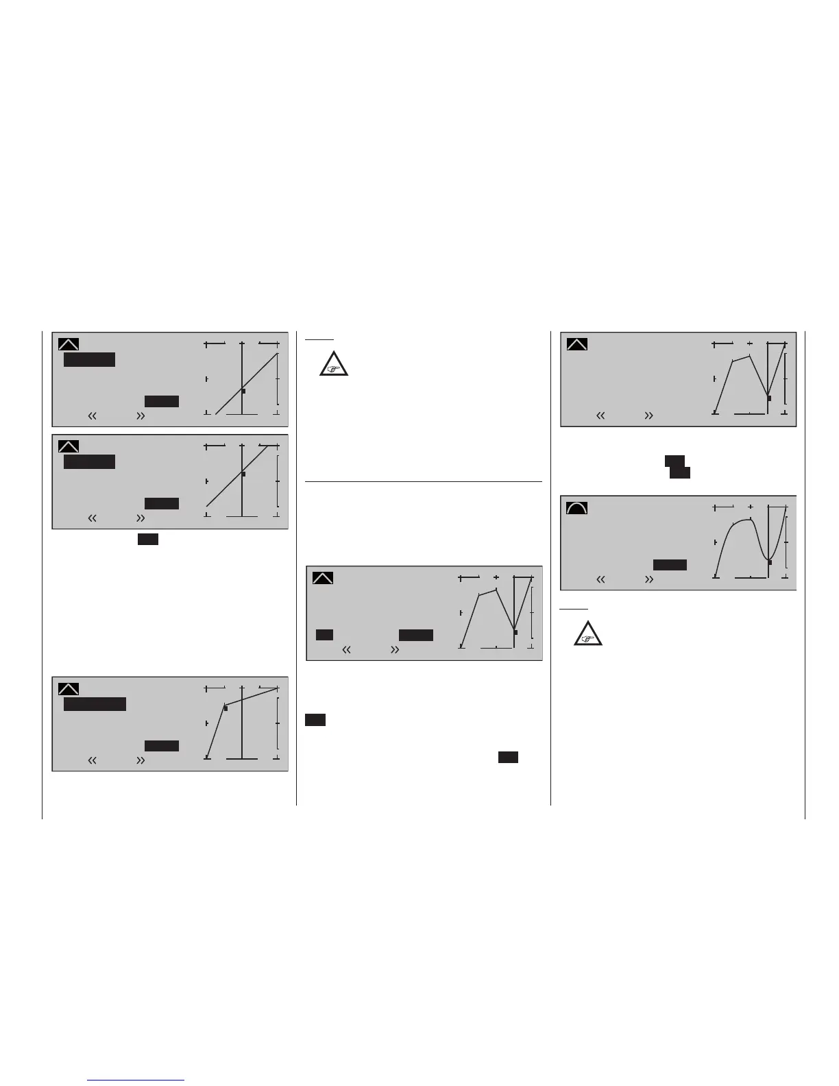
Pitch
Curve
off Point
Output
Input 0%
–25%
1
+
–
100
O U T P U T
–25%
Normal
Trim offset
1
Pitch
Curve
off Point
Outputg
Input 0%
+25%
1
+
–
100
O U T P U T
+25%
Normal
Trim offset
1
A tap on the centre ESC key of the left touch pad will
also terminate this function.
Trim x-axis function
This function is activated by tapping the left () or
right () selection key of the right touch pad with an
active (i. e. inverse video) value field. You can then use
the selection keys on the right touch pad to reposition
the active point horizontally or vertically as you wish.
In the figure below, "Point 1" which was just shifted to
+50 % with the trim point function, will now be shifted
to the left:
Pitch
Curve
off Point
Output
Input 0%
+67%
?
+
–
100
O U T P U T
+50%
Normal
Trim X-axis
1
Notes:
•
If the point is repositioned horizontally
further away from the current control
position than approx. ±25 %, a "?" sign will
reappear in the line Point. This question mark
does not refer to the repositioned point, however:
instead, it signies that a further point can be set
at the current control position.
• Please note that the percentage value on the
"Output" line always relates to the current stick
position and not to the position of the point.
Smoothing the collective pitch curve
In the example below, sample reference points have
been set …
reference point 1 to +50 %,
reference point 2 to +75 % and
reference point 3 to -50 %
… as described in the last section.
Pitch
Curve
off Point
Output
Input +50%
–50%
3
+
–
100
O U T P U T
2
–50%
Normal
1
3
This “jagged” curve profile can be smoothed auto-
matically simply by pressing a button.
Starting from the situation shown in the previous illus-
tration, disable the value field by pressing the central
ESC button of the left-hand touch pad.
Now use the arrow buttons of the left or right-
hand touch pad button to move the marker frame
up to the “Curve” line, and press the central SET
button of the right-hand touch pad button once
more to activate the value field of the “Curve” line:
Pitch
Curve
off Point
Output
Input +50%
–50%
3
+
–
100
O U T P U T
2
–50%
Normal
1
3
Now use the arrow buttons of the right-hand touch
pad to set the Value field from “off” to “on”, and then
briefly press the central SET button of the right-hand
touch pad, or the central ESC button of the left-hand
touch pad, to conclude the procedure:
Pitch
Curve
on Point
Output
Input +50%
–50%
3
+
–
100
O U T P U T
2
–50%
Normal
1
3
Notes:
•
If the stick does not coincide with the
exact reference point, please note that the
percentage value on the "Output" line
always relates to the current stick position.
• The gures on these pages show control curves
created only for the purpose of illustration. Please
note, therefore, that the curve characteristics
displayed do not in any way represent real-life
collective pitch curves. A specic application
example can be found in the programming
examples on page 333.
The following three graphs show typical 3-point pitch
curves for various flight phases, such as hovering,
aerobatics and 3D flight.