195
Program description - Helicopter mixer
Starting and stopping of the mo-
tor – whether combustion or electric
drive – should always take place within the
given ight phase as a consequence of the throt-
tle limiter and the "Thr. CutOff" option in each
single (see below).
This makes it unnecessary to program the two flight
phases that may be familiar to you from using other
remote control systems – namely "with idle-up" and
"without idle-up", and with the associated "waste" of a
flight phase for this purpose – since the
mc-32 HoTT
program offers a much more flexible approach to fine-
tuning and optimizing increases to system rotational
speed below the hover point than the "idle-up" ap-
proach taken by older mc remote control systems.
Ensure that the throttle limiter is closed before start-
ing a motor with carburettor, i. e. so that the carburet-
tor can be adjusted within the idle range only with
trim. Ensure that you follow the safety instructions
on page 189 at all times. If the throttle is set too high
when switching on the transmitter, you will receive
audible and visible warnings!
#02
0:00h
Stoppuhr
Flugzeit
K78
0:00.0
4.1V
0:00.0
00
0
0
00:00h
M
V
Starlet
Thr
too
high!
H-J Sandbrunner
Normal
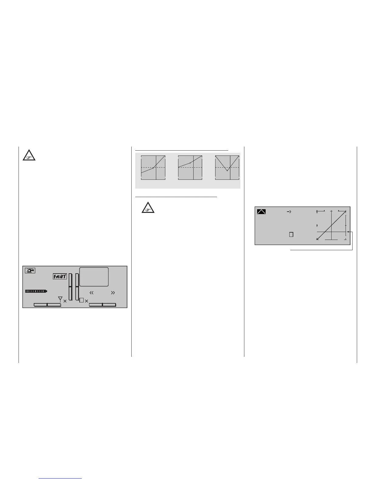
The following three graphs show (typical) 3-point
throttle curves for various flight phases, such as hov-
ering aerobatics and 3D flight.
Sample throttle curves for various ight phases:
+100% +100% +100%
-100%
-100%
-100%
Output
Output
Output
2 3 4 51
2 3 4 51
2 3 4 51
Control travel Control travel Control travel
Hover
Aerobatics 3D
Notes on using the "throttle limit" function:
•
The throttle limit function should be used
in any case (»Control adjust« menu,
page 128). At the rear limit of the default
transmitter control, the right-side throttle limit
proportional rotary slider, the throttle servo is
completely decoupled from the throttle curve, the
motor is at idle and will respond only to C1 trim.
This option permits the motor to be started in any
ight phase and to shut the motor off with the "Thr.
CutOff" option.
Once the motor has started, push the throttle
limiter s l o w l y in the direction of the opposite
end-point to put actuation of the throttle servo fully
under the control of the throttle/collective pitch
stick once again. In order to prevent the throttle
servo from being restricted by the throttle limiter in
the full throttle direction, set control travel on the
plus-side of the column labeled "travel" to +125 %
in the "Tl16" line of the »Control adjust« menu.
Leave the default value of "GL" in the "Type"
column alone, however, to congure this setting
globally for all ight phases.
For a more nely-tuned control travel curve for
the throttle limit control, you can also use the
"Expo throttle limiter" (page 110). This gives
you the option of dening the idle setting at the
throttle limit control's centre position, as readily
determined both visually and audibly.
Set the throttle limiter to its centre position and
adjust the "EXPO thro lim." value as far as is
needed until the motor is idling smoothly with
the throttle limit control set at its centre point. In
this position, the motor will then start without any
problems. To switch off, turn or push the throttle
limit control – that is, without C1 cutoff trim – to its
rearmost end-point. As you do, ensure that the
affected servo cannot hit an end-stop mechanically.
The throttle restriction set by the throttle limiter is
made visible as a horizontal bar in the diagram:
Curve
off Point
Output
Input +50%
+50%
?
+
–
100
O U T P U T
0%
+50%
actual position of the Throttle limiter
Channel 1
Throttle
The output signal for the throttle servo can never
be higher than that set by the horizontal bar. In this
example, about a maximum of +25 %.
• Since electric drive systems have no need for an
idle setting, the basic conguration of settings
for an electrically-powered helicopter merely
involves making sure that the control range of the
throttle limiter is both higher and lower than the
adjustment range of the speed controller (usually
-100 % to +100 %) by a safe margin. If necessary,
therefore, adjust the "travel" setting of the throttle
limiter as appropriate on the "Tl16" line of the
»Control adjust« menu. Leave the default value
of "GL" in the "Type" column alone, however, to
congure this setting globally for all ight phases.
Fine-tuning of the throttle curve itself, however,
must take place in ight – as with a glow-powered
helicopter.