248
Program description - Telemetry
RX FAIL SAFE
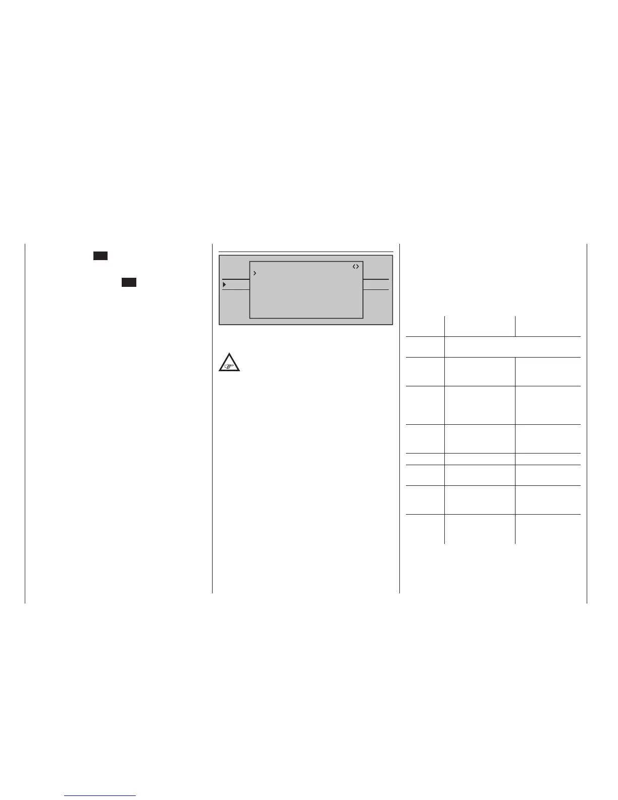
TELEMETRY
SETTING & DATAVIEW
SENSOR SELECT
RF STATUS VIEW
VOICE TRIGGER
TELEMETRI RCV
BIND. 1
RX FAIL SAFE
INPUT CH: 01
MODE : HOLD
F.S.POS. : 1500µsec
DELAY : 0.75sec
OUTPUT CH: 01
FAIL SAFE ALL: NO
POSITION : 1500µsec
The description of this menus necessitates a few
words of warning in advance:
"Do nothing" is the absolute worst thing to be
done in this regard. "HOLD" is prescribed in
the base setup model of the HoTT receiver.
In the event of a failure, in the best case scenario the
model ies straight ahead for an indenite amount of
time and then hopefully "lands" somewhere without
causing signicant damage! However, if something
like this happens in the wrong place at the wrong
time, the model may become uncontrollable and
"tear" across the ight eld completely out of control,
putting the pilot and spectators at risk.
Therefore, it would obviously be benecial to program
the the function "Motor off" at the very least, in order
to prevent such risks. If necessary, seek the advice of
an experienced pilot in order to nd a "logical" setting
for your model.
And then another brief notice regarding the three pos-
sible versions of the
mc-32 HoTT transmitter for
the setting of Fail Safe:
The easiest, and recommended, way to fail-safe set-
tings is the use of the »Fail Safe« menu, which can
be reached from the multifunction menu, see page
224.
Similarly, in order to achieve the same result some-
what more laboriously, the "FAIL SAFE ALL" option
described on the following pages is also available.
In addition, there are the relatively elaborate meth-
ods of the individual adjustment using the options
"MODE", "F.S.Pos." and "DELAY". The description of
these variants begins with the "MODE" option further
below.
Value Explanation
Possible
settings
Vx.xx Receiver’s firmware
version
None
OUTPUT
CH
Output channel
(servo connection
of the receiver)
1 … depending
on receiver
INPUT CH Input channel
(channel
coming from the
transmitter)
1 … max. 12
MODE Fail-Safe mode HOLD
FAIL SAFE
OFF
F.S.POS. Fail-safe position 1000 … 2000 µs
DELAY Reaction time
(delay)
0.25, 0.50, 0.75
and 1.00 s
FAIL
SAFE ALL
Save of the Fail-
safe positions of all
control channels
NO / SAVE
POSITION Display of the
saved Fail-safe
position
Between approx
1000 and 2000 µs
OUTPUT CH (servo connection)
In this line you select the respective OUTPUT CH
(servo connection of the receiver) to be set.
In order to change this value, select the "Centre"
line then touch the SET key. Now move the respec-
tive transmitter control, stick and/or trim wheel to the
desired position and store the current control's posi-
tion with another tap on the SET key. This position is
saved as the new neutral position.
TRIM (trim position)
In the "TRIM" line" you can carry out the fine adjust-
ment of the neutral position of a servo connected to
the control channel selected in the "OUTPUT CH"
line using the selection keys of the right touch pad in
1 µs increments. The value in the "Centre" line can be
adjusted by the TRIM value set here in a range of ±
120 µs.
Factory setting: 0 µs.
LIMIT–/+ (side dependent travel limit -/+)
This option is provided for the adjustment of a side-
dependent limit (limiting) of the servo travel (rudder
throw) of the servo connected to the control channel
selected in the "OUTPUT CH" line.
The settings for both directions are separate but both
are in a range of 30 … 150 %.
Factory setting: 150 % each.
PERIOD (cycle time)
In this line you determine the time interval of the indi-
vidual channel impulse. This setting is adopted for all
control channels.
With the use of only digital servos, a cycle time of
10 ms can be set.
In mixed operation or with use of only analog servos,
20 ms should absolutely be set, because the lat-
ter can otherwise be "over-strained" and react with
"shaking" or "quivering" as a result.