292
Programming examples - Winged models
Model name
Stick mode
1
n/a
BASIC SETTINGS,MODEL
Info
n/a
n/a
Module
bind
HoTT
The "Model name" can now be entered here and,
on the next line, an informative note about the model
can be entered if necessary in the same manner, by a
brief tap on the centre SET key of the right touch pad
to switch to the character table.
!"#$%&’()
Model name
Graub
@ACDEFGHIJKLMNOPQRSTUVWXYZ[¥]^_
?+,–./0123456789:;
¢ÇüéâäàåçêëèïîìÄÅÉæÆôöòûùÖÜ
`abcdefghijklmnopqrstuvwxyz{|}~
The pre-sets for "Stick mode", "Modulation" and
"DSC Output" are adopted from data stored in the
»General basic settings« menu and these should
be reviewed and changed as necessary.
In the menu …Model type
Tail type
Motor on C1
Normal
None
Aileron/camber flaps
1 AIL
M O D E L L T Y PE
Brake Offset Input 1+100%
SEL
… the principle arrangement of the servos in the
model is selected and communicated to the transmit-
ter.
The following selections are available:
"Motor at C1"
• "none"
Trimming works independently of the stick position
and the "Brake settings" sub-menu of the »Wing
mixers« menu (beginning page 185), is available
without limitation.
The "Throttle too high" warning message, see
page 33 and/or 104, and the "Motor stop" option
of the »Model basic setting« (page 90) are
deactivated.
• "(Idle) front or rear“
C1 trimming is affected in the front or rear and the
"Motor stop" option is activated.
If the throttle stick is too far in the full throttle
direction when the transmitter is switched on,
this will be indicated with the warning message
"Throttle too high".
In parallel with this, the "Brake settings" sub-menu
of the »Wing mixers« menu, beginning page 185,
will only then be available if the "Motor" column of
the »Phase settings« menu, page 154, has the
entry "none" for the currently active flight phase.
In the next two lines, the principle arrangement of the
servos in the model is selected and communicated to
the transmitter:
Tail type
Motor on C1
Normal
None
Aileron/camber flaps
1 AIL
M O D E L L T Y PE
Brake Offset Input 1+100%
SEL
• Tail type
"normal", "V-tail", "Delt/fl.wing" or "2 Sv EL 3+8"
• Aileron/camber aps
1, 2 or 4 AI servos and 0, 1, 2 or 4 FL servos
Since we want to actuate the brake system of the
"Brake settings" sub-menu under the »Wing mix-
ers« menu with the C1 stick, we will leave the outer
right setting in the "Brake Offset" line with "Input 1".
With the "Offset value" to the left of this, you should
only place the mixer neutral point at the point where
the brake system is retracted or inactive. If, in the
process, the offset is not place completely at the end
of the control path, the rest of the path is "idle travel",
which means the mixer is not influenced in this range
of the stick movement.
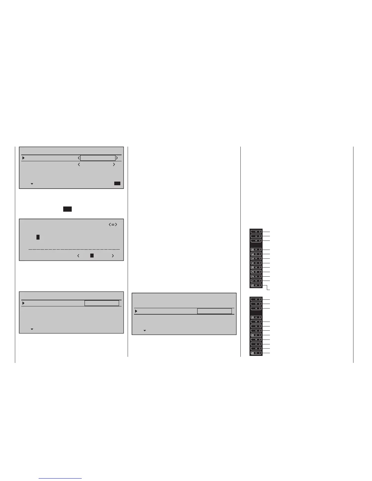
By now at the latest, servos should be plugged into
the receiver in the standard Graupner’ish sequence:
Receiver power supply
free or AIL2 left or aux. function
free or AIL2 right or aux. function
Rudder
Aileron or left aileron
Elevator or 1st elevator
free or 2nd Elevator or aux. function
Receiver power supply
Airbrake or throttle servo
or speed controller (electric motor)
Right aileron or aux. function
Flap or left flap
Right flap or free or aux. function
free or left flap2 or aux. function
free or flap2 right or aux. function
13 14 T
15 16
S
77
8
9
10 11 12
Receiver power supply
free or aux. function
free or aux. function
Telemetry connection
Receiver power supply
free or aux. function
free or aux. function
SUMO / SUMI-connection
Receiver power supply
Receiver power supply