301
Programming examples - Winged models
Now move the marker frame once more to the right
and enter an appropriate switching time after activa-
tion of the value field of the "Sw.Time" column; for
example:
Phase 1
Phase 2
Phase 3
Phase 4
Phase 5
Name Timer
Sw.time
Motor
yes
1.1s
no
1.1s
yes
0.1s
yes
0.1s
yes
0.1s
–
–
–
–
Normal Clk1
Landing
Then you must assigned these two flight phases to
a switch with which you can switch between the two
flight phases during the flight. In this case, a single
switch is sufficient. It should be easy to reach, how-
ever, so that you can still switch between "motor"
and "brake" during a landing approach, for example,
without having to release a stick.
The assignment of the selected switch takes place in
the menu …
»Phase assignment« (page 160)
Select the switch symbol under "C" with one of the
selection keys. Following a brief tap on the centre
SET key of the right touch pad, actuate the desired
switch, e.g "2".
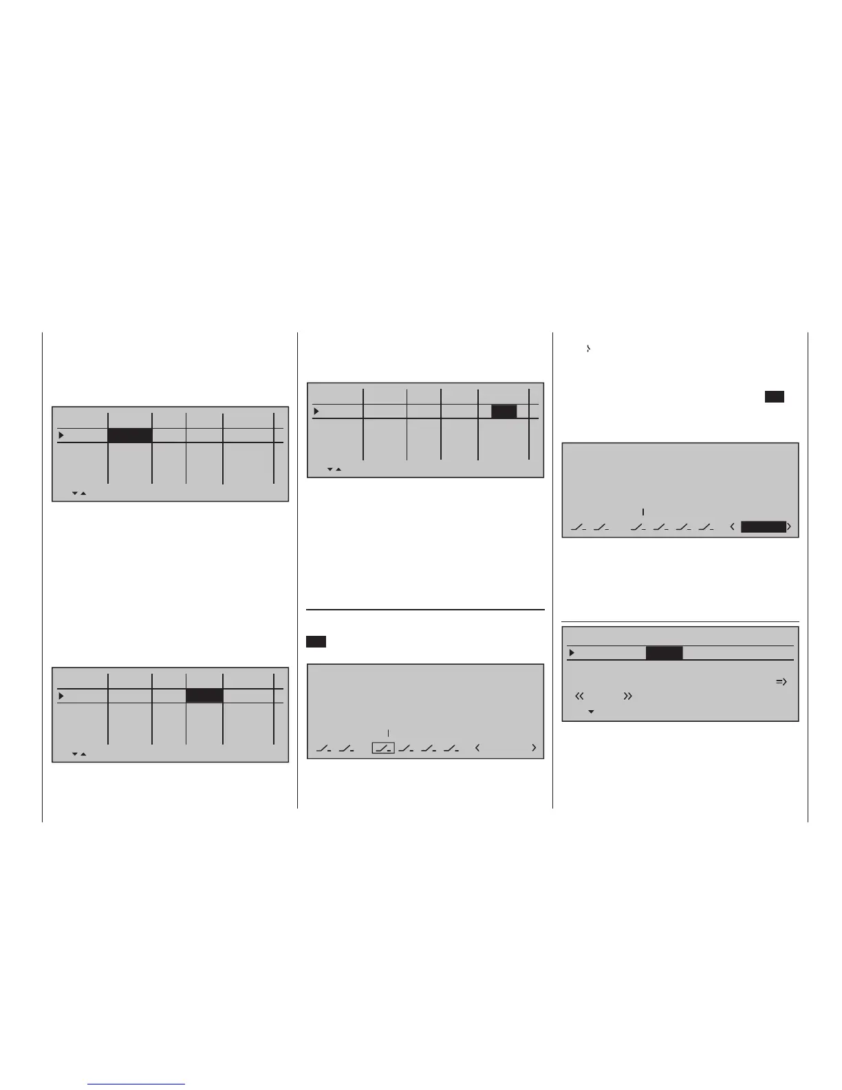
P H A S E ASSIGNMENT
Prior .
C
1 Normal
combi
A
B D E F
2 7
2
In the "Ph.Tim" column you can assign a so-called
flight phase timer for the measurement of the motor
running time and/or the gliding times as necessary for
each phase. You could, for example, assign one of the
"Timers 1 … 3" to the "Normal" flight phase in order
to measure the total motor runtime via the C1 stick:
Phase 1
Phase 2
Phase 3
Phase 4
Phase 5
Name Timer
Sw.time
Motor
yes
0.1s
yes
0.1s
yes
0.1s
yes
0.1s
yes
0.1s
–
–
–
–
Normal Clk1
Landing
Then the timer is controlled through a corresponding
control switch to be defined on the C1 stick. As soon
as you switch to the "Landing" flight phase, this flight
phase timer is automatically stopped and hidden in
the base screen. More about this can be found on
page 168.
Now move the marker frame over the "Ph.Tim" col-
umn to the "Motor" column to the right. Here you
can decide with "yes/no" in which phase the motor
is controlled by the throttle/brake stick and the brake
system to be adjusted in the "Brake settings" sub-
menu of the »Wing mixers« menu (page 185) should
be shut off (= "yes") and vice versa (= "no"):
Phase 1
Phase 2
Phase 3
Phase 4
Phase 5
Name Timer
Sw.time
Motor
yes
0.1s
no
0.1s
yes
0.1s
yes
0.1s
yes
0.1s
–
–
–
–
Normal Clk1
Landing
Both switch positions, in other words ON (I) and
OFF ( ), are initially assigned at the bottom right of
the display to phase «1 Normal». Select this value
field with one of the selection keys then activate the
phase selection list that was set up in the »Phase
settings« menu with a brief tap on the centre SET
key of the right touch pad. For example, you name the
phase for the front switch position "normal" and "land-
ing" for the rear position (or vice versa):
P H A S E ASSIGNMENT
Prior.
C
combi
A
B D E F
2 7
2
2Landing
These phase names then appear in all flight-phase
dependent menus and, of course, also in the base
screen of the transmitter.
Now switch to the «Landing» flight phase and in the
"Crow" line of the sub-menu …
»Brake settings« (page 185)
Elevat. curve
BRAKE SETTINGS
Landing
Crow
QR
WK2
0%
WK
0%
Diff. reduct.
0%
… of the »Wing mixers« menu, set the desired throw
of the ailerons by actuation of the C1 stick ("brake")
upward.