335
Programming examples - Helicopter models
pre-setting of 0 % at point "L" (minimum pitch) to
-30 % and at the opposite end, at point "H" to +30 %
(maximum pitch). These values may have to be cor-
rected in flight. It may also be necessary to set point
"1" in the middle.
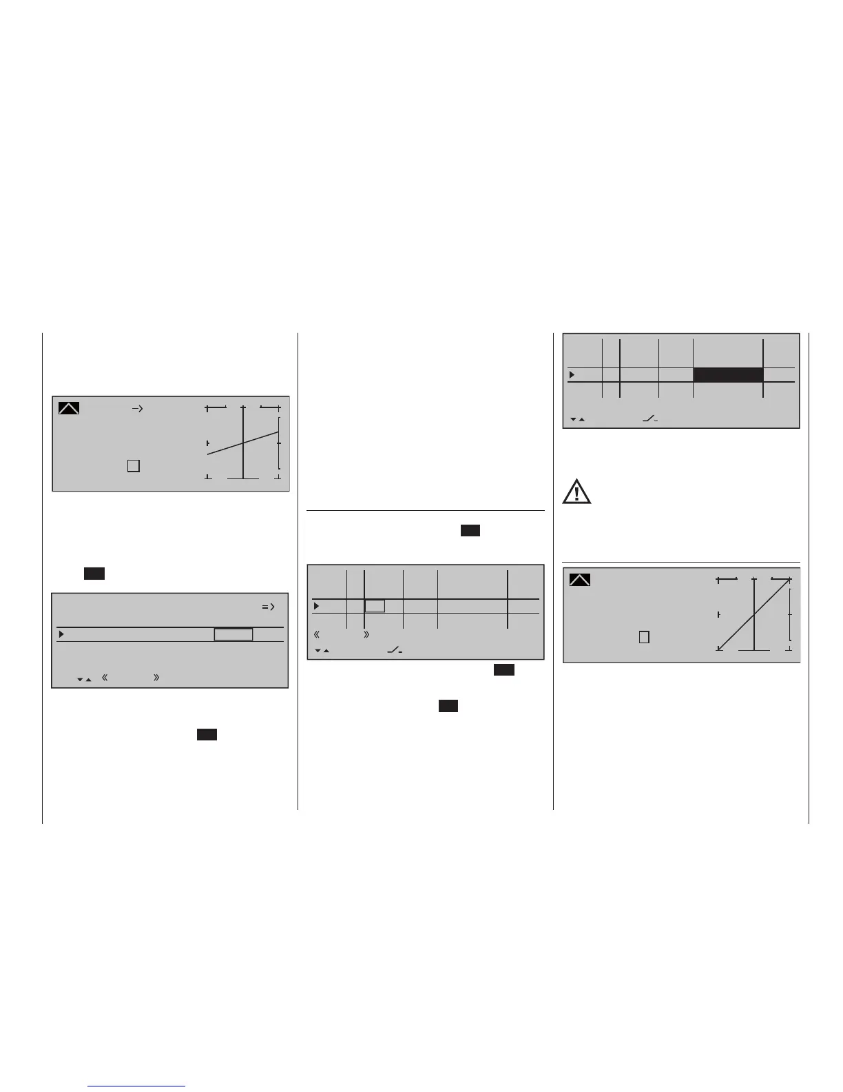
Channel 1
Curve
off Point
Output
Input 0%
0%
?
+
–
100
O U T P U T
0%
Tail rot.
Now, for testing purposes, switch back to the auto-
rotation phase. Here the setting is also deactivated;
the tail servo no longer reacts to pitch movements
(no torque usually arises when the main rotor is not
powered). All additional interpolation points are not
currently of importance yet. Navigate by pressing the
central ESC button of the left-hand four-way button
one level up:
Pitch
–125%
Tail rot. offset AR
0%
Throttle position AR
Gyro suppression
0%
Gyro offset 0%
SEL
Autorot
Set the helicopter horizontally on with the engine off.
With activated transmitting and receiving system, fold
the tail rotor blades down and change the line “Tail
rotor AR” by pressing the central SET key of the right
four-way button to activate the value field, until the
value of the tail rotor blades angle is zero degrees.
The tail rotor blades are then viewed from behind
parallel.
Depending on the friction and running resistance of
the gearbox, it may be that the fuselage still rotates
slightly. This relatively weak torque must be corrected
on the tail rotor blade pitch then optionally. In any
case, this value is between zero degrees and a pitch
angle opposed to the direction of tail rotor pitch re-
quired for normal flight.
All other sub-items are not currently important. There-
fore switch back to the normal phase.
If, contrary to the default setting, the gyro has a
transmitter-side sensitivity setting, another free pro-
portional control will be needed.
This can be assigned in the …
»Control adjust« (page 122)
… menu to "Gyr7" input. Activate the control assign-
ment with a brief tap on the centre SET key of the
right touch pad then move the selected control until
its control number appears in the display:
0%
I5 +88%
Thr6
Gyr7
I8
Ty p
+111%
– travel + –time+
0%
+100%
+100%
0.0 0.0
0%
+100%
+100%
0.0 0.0
0%
+100%
+100%
0.0 0.0
GL
GL
GL
fr
Sl1
fr
---
---
---
offset
GL
Normal
0.0 0.0
SET
fr ---
Conclude this entry with a brief tap on the ESC key of
the left touch pad then change to the column "- travel
+" with the selection key of the left or right touch
pad. After a tap on the centre SET key of the right
touch pad, the gyro's maximum sensitivity can be set
in the value field displayed in inverse video, e. g. to
50 %. To this end, move the selected control into its
middle position or, if applicable also to the side, such
that only one value field is displayed in inverse video:
0%
I5 +88%
Thr6
Gyr7
I8
Ty p
+111%
– travel + –time+
0%
+100%
+100%
0.0 0.0
0%
0.0 0.0
0%
+100%
+100%
0.0 0.0
GL
GL
GL
fr
Sl1
fr
---
---
---
offset
GL
Normal
0.0 0.0
SET
fr ---
+50%
+50%
This produces a fixed value for as long as the control
remains at the right limit position. The correct value
must be adjusted in flight.
In the process, however, always observe
the adjustment instructions accompany-
ing your gyro sensor, because your heli-
copter will not be able to y otherwise!
To conclude this initial programming, a few words
should be mentioned about the menu …
»Channel 1 curve« (page 143)
Channel 1 CURVE
Curve
off Point
Output
Input 0%
0%
?
+
–
100
O U T P U T
0%
This function is a type of "convenient exponential
curve" for the throttle/pitch stick and the mixer func-
tions connected to it.
If ever, this curve should only be applied "cautiously"
at the very end, when all adjustments have been
made. It should never be used for the throttle/pitch
adjustment! The over-lapping result in "nasty" effects.