38
Transmitter description - Secret mode
1
3
5
7
9
11
13
15
0
0
0
0
0
0
0
0
–50
0
0
0
0
0
0
0
2
4
6
8
10
12
14
16
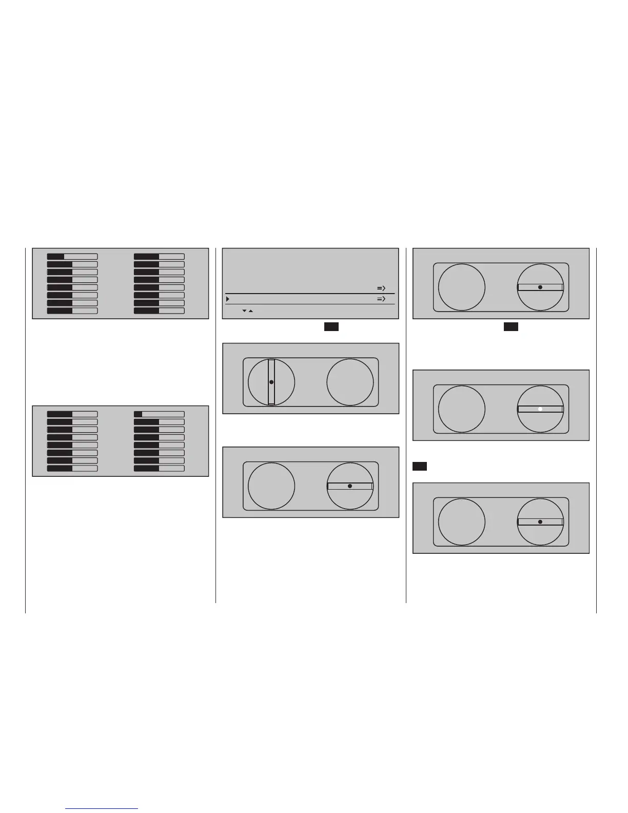
One after the other, put both sticks into each of their
four possible limit positions without exerting force at
the limit position. In each of these eight possible limit
positions, the – side dependent – indication for exactly
-100 % or +100 % should be displayed. For example,
if transmitter control 2 is at its right limit and the other
three stick functions are in their respective middle
positions then the transmitter's display should look
like the one shown below.
1
3
5
7
9
11
13
15
–100
0
0
0
0
0
0
0
0
0
0
0
0
0
0
0
2
4
6
8
10
12
14
16
Regardless of the number of self-neutralizing stick
functions available on your transmitter, if these checks
produce four 0 % results and eight 100 % results then
your transmitter's sticks are optimally calibrated. You
can terminate this process then, if appropriate, delete
the model memory just created.
Otherwise jump (as described at the outset of the
previous double page) to the "Stick calibration" line in
the »SECRET MODE« menu...
SECRET MODE
BOTTOM LCD CONTRAST
FIRMWARE UPDATE
0
STICK CALIBRATION
VOICE UPDATE
0
... then briefly touch the centre SET key of the right
touch pad.
STICK CALIBRATION
0%
The selection keys of the right touch pad will now
allow you to cyclically select the four calibrated stick
planes, e. g. the left/right plane of the right stick.
STICK CALIBRATION
0%
Now position the right stick – without exerting extra
force – to its left limit corresponding with the on-screen
blinking arrow pointing to the left.
STICK CALIBRATION
+102%
… and briefly tap the centre SET key of the right touch
pad. This concludes this example calibration of the
right stick's left limit. The circle in the middle of the
stylized stick plane will now blink as confirmation of the
calibration.
STICK CALIBRATION
+100%
Now release the self-neutralizing stick so it can return
to its centre position and then tap again on the centre
SET key to calibrate the stick's centreed position. The
right triangle marker will begin to blink.
STICK CALIBRATION
0%
Repeat the calibration process for the right limit of the
right stick. The other stick planes are calibrated analo-
gously.