86
Program description - Base setup models | Winged models
are all the HoTT-specific displays in the base display;
“PPM” is also superimposed instead of “HoTT”:
#01
0:00h
Stop watch
Flight time
K78
0:00.0
4.1V
0:00.0
RX VOLT:0.0v
00
0
0
00:00h
M
V
PPM
Graubele
H-J Sandbrunner
SP mode (Digital signal at DSC sock-
et)
If you need for external RF module from another
manufacturer, or however, instead of the analog PPM
signal a special digital signal, then connect it to the
DATA jack and select the line “module” to “SP Mode”:
Model name
Stick mode
1
BASIC SETTING,MODEL
Info
Module
Graubele
1234g/111111
SEL
SP mode
MOD BD
1 bind
Also include here the choice by pressing the central
SET key of the right or the centre ESC key of the left
touch pad.
Parallel to this choice are also the options described
below “Receiver output” and “Range Test” and hidden
all HoTT-specific displays in the basic display and
instead of “HoTT”, “SP” is displayed:
#01
0:00h
Stop watch
Flight time
K78
0:00.0
4.1V
0:00.0
RX VOLT:0.0v
00
0
0
00:00h
M
V
SP
Graubele
H-J Sandbrunner
“Mode” column
Model name
Stick mode
1
BASIC SETTING,MODEL
Info
Module
Graubele
1234g/111111
SEL
SP mode
MOD BD
1 bind
In this column you select the transmission mode of
the external RF module:
• Mode “1”: 2-channel hopping
• Mode “2”: x-channel hopping
“BIND” column
Model name
Stick mode
1
BASIC SETTING,MODEL
Info
Module
Graubele
1234g/111111
SEL
SP mode
MOD BD
1 bind
The “BIND” column in the right-hand column can be
used to initiate the “Bind” process of the non-Graup-
ner system – the transmitter’s RF section must be
switched off when the transmitter is rst switched
on.
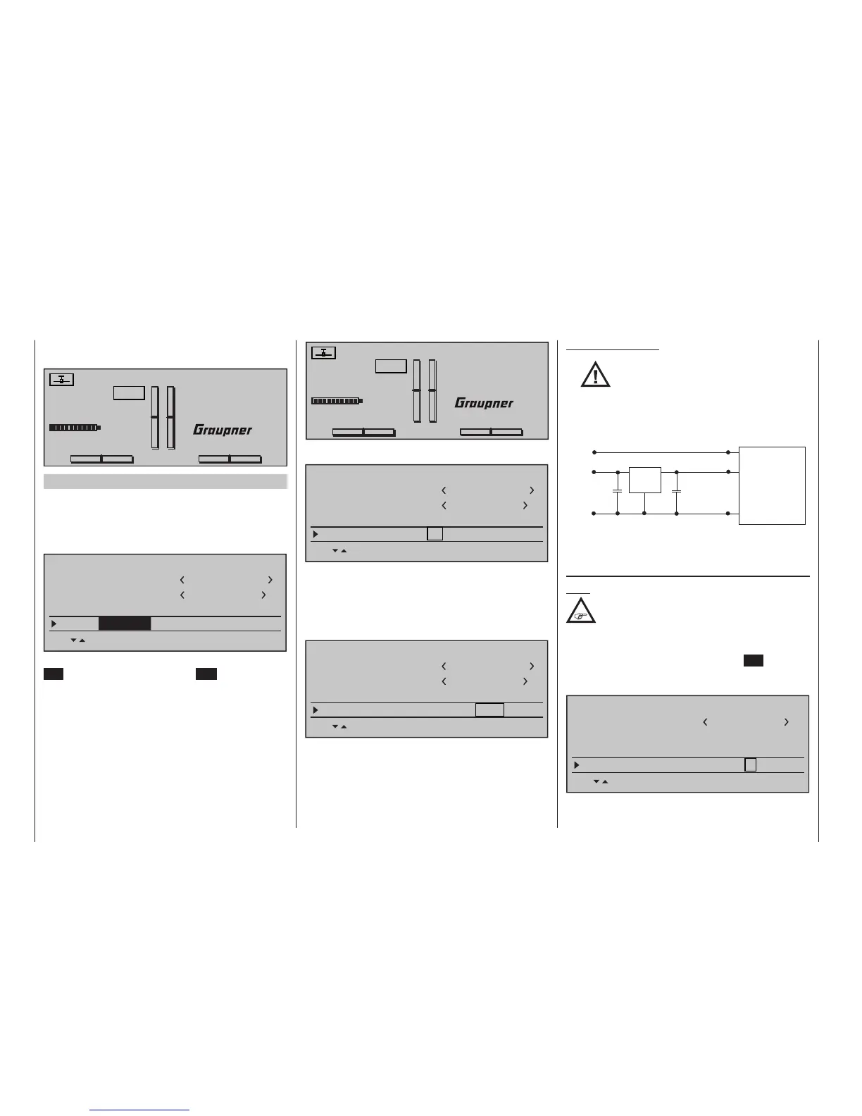
Important notes:
•
The output voltage of the DATA
socket is around 5 V, and must be
reduced to the power supply
voltage generally required by external
digital RF modules (3 to max. 3.3 V). This
is accomplished using the circuit which
is shown here in diagrammatic form:
GND
Vcc IN = 5 V
DATA +
DATA S
125000 baud signal
Vcc
GND
DATA -
22µF/6.3 V
22µF/6.3 V
Vcc OUT = 3 ... 3.3 V
Low Drop
Voltage
Regulator
SP.-MODULE
with
digital input signal
• Servo travels must be limited to max.
128 %.
SP channels
Note:
This menu line is suppressed in the “Module”
line if you select “HoTT” or “EXT.”.
If necessary, use the Select buttons of the left or
right-hand four-way button to move to the “SP chan-
nels” line, then briefly press the central SET button of
the right-hand four-way button to activate the Value
window:
Stick mode
1
BASIC SETTING,MODEL
Info
Module
1234g/111111
SEL
bind
1
SP module
SP channels
6