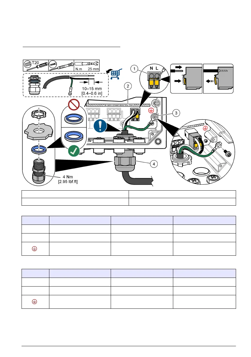
Refer to Figure 9 and Table 2 or Table 3 to connect conduit or a power cord. Insert each wire into the
appropriate terminal until the insulation is seated against the connector with no bare wire exposed.
Tug gently after insertion to make sure that there is a secure connection. If necessary, remove the
connector from the PCBA for easier wiring of the terminals.
Note: Make sure that all of the cables stay below the cable limit line printed on the PCBA to prevent interferences
with the high-voltage barrier. Refer to Figure 9.
Figure 9 Connect conduit or a power cord
1 AC and DC power terminal 3 Protective earth ground
2 Cables limit: do not put cables above the line. 4 Conduit hub (or strain relief fitting for power cord)
Table 2 Wiring information—AC power
Terminal Description Color—North America Color—EU
L Hot (Line 1) Black Brown
N Neutral (N) White Blue
Protective earth ground Green Green with yellow stripe
Table 3 Wiring information—DC power
Terminal Description Color—North America Color—EU
L +24 VDC Red Red
N 24 VDC return Black Black
Protective earth ground Green Green with yellow stripe
English 17

 Loading...


