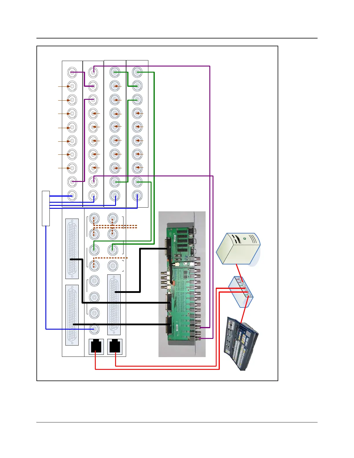
Figure 4-6. IconMaster System with Internal (Single Channel) Audio and Video NSM Internal
REF
INPUT
OUT 1 IN 1 IN 2 IN 3 IN 4 IN 5 IN 6 IN 7 OUT 2
NSM-7X2SHD-BM
REF
INPUT
OUT 1 IN 1 IN 2 IN 3 IN 4 IN 5 IN 6 IN 7 OUT 2
NSM-7X2SHD-BM
REF
INPUT
OUT 1IN 1IN 2IN 3IN 4IN 5IN 6IN 7OUT 2
NSM-7X2AES-BM
REF
INPUT
OUT 1IN 1IN 2IN 3IN 4IN 5IN 6IN 7OUT 2
NSM-7X2AES-BM
Ethernet Switch
IconMaster
Control Panel
PC loaded with
IconMaster Soft Tools
Station Reference*
Ext
Key 1
Input 1 Input 2 Input 3 Input 4 Input 5
Input 6 Input 7 Input 8 Input 9 Input 10 Input 11 Input 12
MKA-3901-B-BM
AES Input AES Output
Genlock
Clean PGM PST
Squeeze
Bkgd
Bus A Key 1 Fill 2
Fill 1 Key 2Bus BPGM
MKE-3901-BM
Multi Function I/O
Outputs Inputs
InputsOutput
Ethernet 1
Ethernet 2
Optional ICONM-BO-VAC shown
Input 1 Input 2 Input 3 Input 4 Input 5
Input 6 Input 7 Input 8 Input 9 Input 10 Input 11 Input 12
Ext
Key 2
Video NSMs Audio NSMs
MKE breakout cable
165-000242Q00
MKA
Breakout
cables
165-000243Q00
FX squeeze
background
Connect to BUS A IN 1
Connect to BUS B IN 1
C
o
n
n
e
c
t
t
o
E
t
h
e
r
n
e
t
2
* The same station reference must be used for all reference
inputs, either using loop thru or distribution amplifier.