78 IconMaster Installation and Configuration Manual
Chapter 4: Router Connections
Sample Configuration 1: IconMaster System with Internal
Video NSM Router and Optional ICONM-BO-V Module
This section describes the connections that are required in a typical
configurations involving an IconMaster system with an NSM video router
module and an optional breakout module. You can place the NSM modules
anywhere in the same NEO frame as the IconMaster system. Figure 4-3 on
page 79 shows a detailed illustration of this process.
1. Configure the NEO NSM Module
1. Set the NEO NSM back module to Unterminated reference:
a. Remove the NSM back module from the NEO frame.
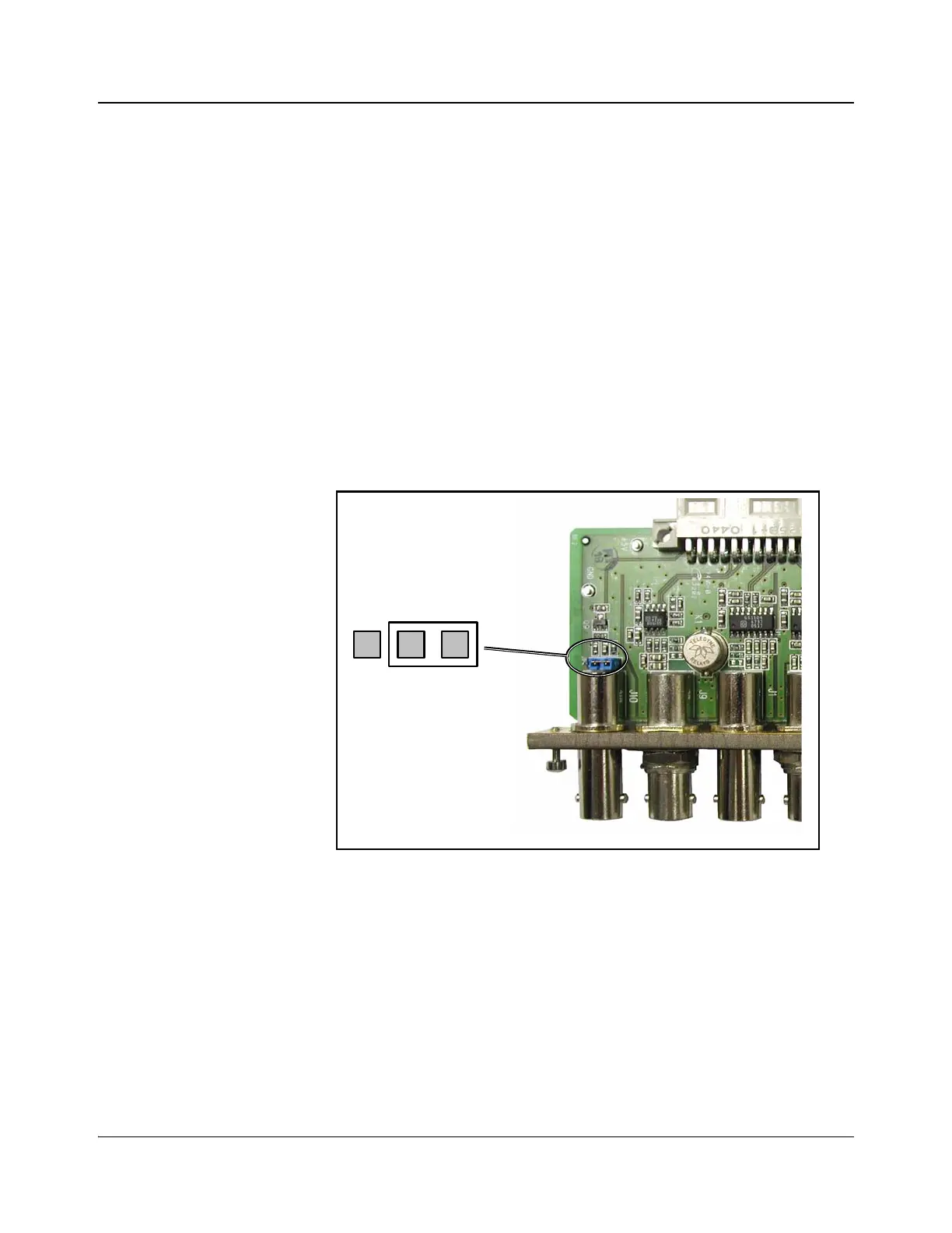
b. Locate jumper JP1 on the NEO NSM back module (see Figure 4-2),
and then set the NEO NSM back module to Unterminated reference by
setting JP1 as shown.
c. Reinstall the NSM back module into the NEO frame.
Figure 4-2. Jumper JP1 on the NSM Back Module
2. Connect a maximum of 7 video inputs to the BNC connections labeled In 1
to In 7.
3. Connect Out 1 on the NSM to Input Bus A on the MKE-3901.
4. When using the ICONM-BO-VAC breakout module and NSM routers,
audio output 1 from the NSM router must be connected to Bus A In 1 on
the breakout module as indicated in Figure 4-4 on page 80.
When using the ICON-BO-VAB breakout module and NSM routers, the
audio output 1 from the NSM router must be connected to Input Bus A1 on
the breakout module as indicated in
Table 2-9 on page 54.
Jumper JP1 set to
Unterminated