20 IconMaster Installation and Configuration Manual
Chapter 2: Installation
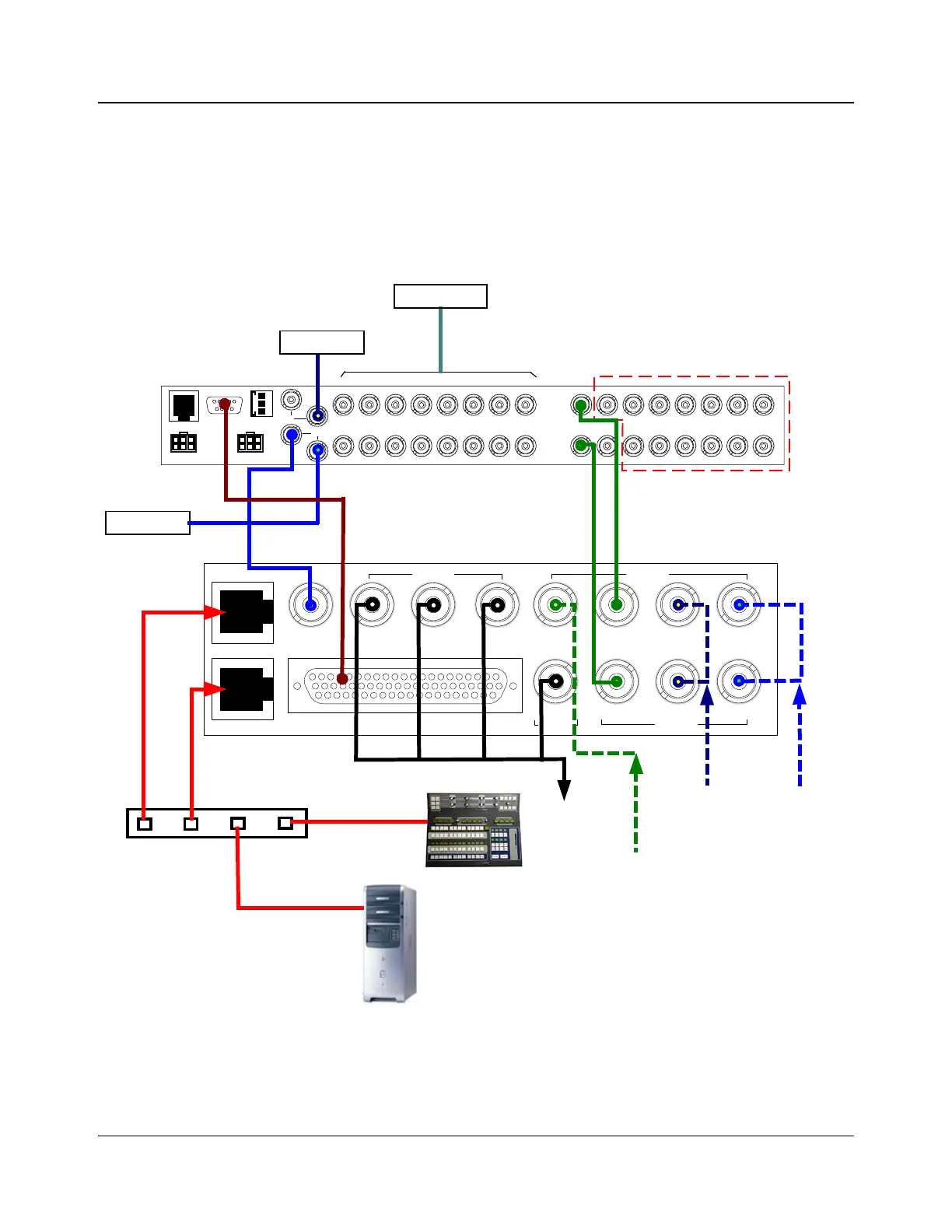
Sample System Layout
Figure 2-2 shows a sample system layout that includes an external router, PC,
Ethernet switch, and IconMaster system. For illustrations of sample system
layouts for NEO routers, see “System Configurations—NEO Routers” on page
77. For illustrations of sample system layouts for Panacea routers, see “System
Configurations—Panacea Routers” on page 91.
Figure 2-2. Sample System Layout
XY
POWER
PS1
19
4
5
6
7
10
SERIAL
ENET
POWER
PS2
ALM/COM
SYNC
2
3
8
11
12
13
14
15
16
19
4
5
6
7
102
3
8
11
12
13
14
15
16
INPUT OUTPUT
Terminated
Station reference
Primary inputs
Router outputs available for
Aux purposes
Genlock
Clean PGM PST
Squeeze
Bkgd
Bus A Key 1 Fill 2
Fill 1 Key 2Bus BPGM
MKE-3901-BM
Multi Function I/O
Outputs Inputs
InputsOutput
Ethernet 1
Ethernet 2
Ethernet switch
IconMaster
control panel
PC with:
y LogoCreator
y Content Editor
y IconSet
y IconLogo Soft Panel
IconMaster Configuration Utility
Video
outputs
FX squeeze
background
CG 2 (Key 2)
CG 1
Ethernet 2
connector
Panacea 16x16 router
RS-232
RS-422
MKE-3901
MGI-3903