76 IconMaster Installation and Configuration Manual
Chapter 4: Router Connections
Sample System Layout
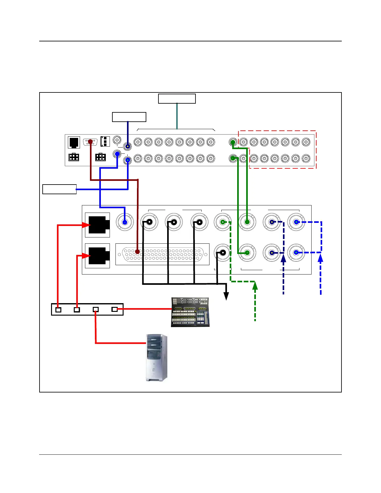
Figure 4-1 shows a sample system layout that includes a router, PC, Ethernet
switch, and IconMaster system.
Figure 4-1. Sample System Layout
XY
POWER
PS1
19
4
5
6
7
10
SERIAL
ENET
POWER
PS2
ALM/COM
SYNC
2
3
8
11
12
13
14
15
16
19
4
5
6
7
102
3
8
11
12
13
14
15
16
INPUT OUTPUT
Terminated
Station reference
Primary inputs
Router outputs available for
Aux purposes
Genlock
Clean PGM PST
Squeeze
Bkgd
Bus A Key 1 Fill 2
Fill 1 Key 2Bus BPGM
MKE-3901-BM
Multi Function I/O
Outputs Inputs
InputsOutput
Ethernet 1
Ethernet 2
Ethernet switch
IconMaster
control panel
PC with:
y LogoCreator
y Content Editor
y IconSet
y IconLogo Soft Panel
IconMaster Configuration Utility
Video
outputs
FX squeeze
background
CG 2 (Key 2)
CG 1
Ethernet 2
connector
Panacea 16x16 router
RS-232
RS-422
MKE-3901
MGI-3903