92 IconMaster Installation and Configuration Manual
Chapter 4: Router Connections
Sample Configuration 1: IconMaster System, External Panacea
Video Router, Optional ICONM-BO-V Module
This section describes the connections that are required in a typical
configurations involving an IconMaster system with a Panacea video router and
an optional breakout module. Figure 4-12 on page 93 shows a detailed
illustration of this process.
1. Configuring the Panacea Router
Before you can make any connections to an IconMaster, the Panacea router
must already be configured as desired. If your Panacea router is already
operational, you do not need to configure it. If, however, your Panacea router is
not already operational, you must install and configure it as desired for your
facility. See the Panacea Series Frame and Modules Installation,
Configuration, and Operation Manual for detailed information.
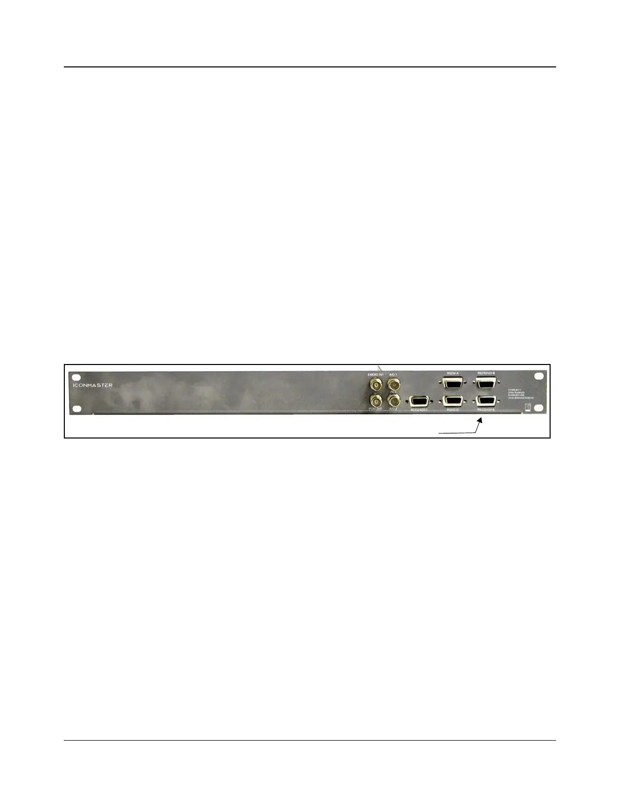
2. Make Connections on the Panacea and ICONM-BO-V Breakout Module
When using the ICONM-BO-V breakout module, the serial port of the Panacea
router must be connected to the RS-232/422-E port on the breakout module as
indicated in Figure 4-11.
Figure 4-11. RS-232/422-E Port on the ICONM-BO-V Breakout Module
3. Make Connections on the Panacea and MKE-3901
1. On the Panacea back module, connect a maximum of 16 video inputs to the
BNC connections labeled Input 1 to Input 16.
2. Connect Output 1 on the Panacea to Input Bus A on the MKE-3901.
3. Connect Output 2 on the Panacea to Input Bus B on the MKE-3901.
4. Connect your station reference to the Sync connection of the Panacea back
module.
5. Terminate one of the XY BNC connectors on the Panacea router.
6. Connect the serial port of the Panacea router to Serial Port E in the Multi
Function I/O connector on the MKE-3901.
This can be done in either of these two ways.
• Direct connection
• ICONM-BO-V breakout module connection
7. On the MKE-3901 back module, connect the Key 1 input source to Key 1
and Fill 1 as appropriate.