106 IconMaster Installation and Configuration Manual
Chapter 4: Router Connections
Sample Configuration 4: IconMaster System, External Panacea
(Single Channel) Audio and Video Routers, Optional
ICONM-BO-VAC Module, Optional SPT-LSERIAL
This section describes the connections that are required in a typical
configuration involving an IconMaster system with a single channel Panacea
audio and video routers, an optional breakout module, and an optional
SPT-LSERIAL serial protocol translator. Figure 4-20 on page 107 shows a
detailed illustration of this process.
1. Configure the Panacea Router
Before you can make any connections to an IconMaster, the Panacea router
must already be configured as desired. If your Panacea router is already
operational, you do not need to configure it. If, however, your Panacea router is
not already operational, you must install and configure it as desired for your
facility. See the Panacea Series Frame and Modules Installation,
Configuration, and Operation Manual for detailed information.
2. Make Connections on the Panacea and ICONM-BO-VAC Breakout Module
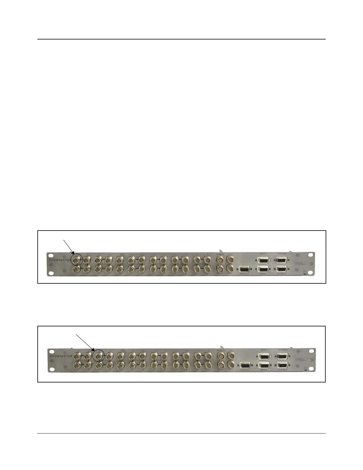
When using the ICONM-BO-VAC breakout module and multiple Panacea
routers (multi-level), the audio output 1 from the level 1 Panacea router must be
connected to Bus A In 1 on the breakout module as indicated in Figure 4-18.
Figure 4-18. Audio 1, Level 1 Panacea Connection to ICONM-BO-VAC
Likewise, the audio output 2 from the level 1 Panacea router must be connected
to Bus B In 1 on the breakout module as indicated in Figure 4-19.
Figure 4-19. Audio 2, Level 1 Panacea Connection to ICONM-BO-VAC