IconMaster Installation and Configuration Manual 107
Chapter 4: Router Connections
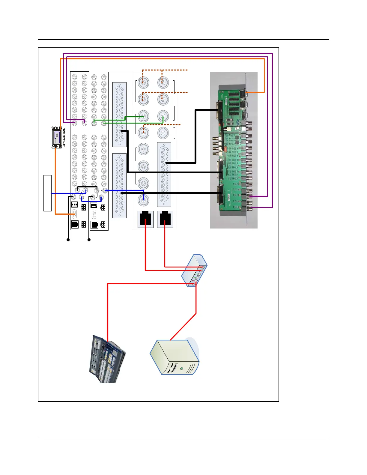
Figure 4-20. IconMaster System with External Panacea (Single Channel) Audio and Video Routers,
Optional ICONM-BO-VAC Module, Optional SPT-LSERIAL
MKA-3901-B-BM
AES Input AES Output
Genlock
Clean PGM PST
Squeeze
Bkgd
Bus A Key 1 Fill 2
Fill 1 Key 2Bus BPGM
MKE-3901-BM
Multi Function I/O
Outputs Inputs
InputsOutput
Ethernet 1
Ethernet 2
Ethernet Switch
IconMaster
Control Panel
PC loaded with
IconMaster Soft Tools
Station Reference*
Ext Key 1 Ext Key 2
Connect to Ethernet 2
FX squeeze
background
XY
POWER
PS1
19
4
5
6
7
10
SERIAL
ENET
POWER
PS2
ALM/COM
SYNC
2
3
8
11
12
13
14
15
16
19
4
5
6
7
102
3
8
11
12
13
14
15
16
INPUT OUTPU T
Connect to RS232/422-E
Terminated
Optional ICONM-BO-VAC shown
MKE breakout cable
165-000242Q00
XY
POWER
PS1
19
4
5
6
7
10
SERIAL
ENET
POWER
PS2
ALM/COM
SYNC
2
3
8
11
12
13
14
15
16
19
4
5
6
7
102
3
8
11
12
13
14
15
16
INPUT OUTPU T
Terminated
Video
Router
Audio
Router
MKA
breakout cables
165-000243Q00
Connect to BUS A IN 1
Connect to BUS B IN 1
same station reference must be used for all reference
, either using loop thru or distribution amplifier.