108 IconMaster Installation and Configuration Manual
Chapter 4: Router Connections
Audio output 1 from the level 2 Panacea router must be connected to Bus A In
2 on the breakout module, as indicated in Figure 4-21.
Figure 4-21. Audio 1, Level 2 Panacea Connection to ICONM-BO-VAC
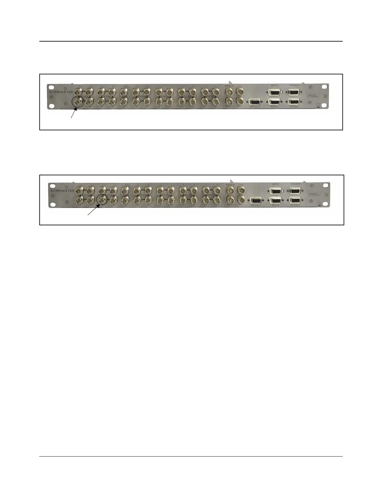
Audio output 1 from the level 2 Panacea router must be connected to Bus B In 2
on the breakout module, as indicated in Figure 4-22.
Figure 4-22. Audio 2, Level 2 Panacea Connection to ICONM-BO-VAC
When using the ICON-BO-VAB breakout module and a Panacea router (single
level), audio output 1 from the Panacea router must be connected to Input Bus
A1 on the breakout module as indicated in Table 2-9 on page 54.
Likewise, audio output 2 from the Panacea router must be connected to Input
Bus B1 on the breakout module as indicated in Table 2-9 on page 54.
Audio output 1 from the level 2 Panacea router must be connected to Input Bus
A2 on the breakout module as indicated in Table 2-9 on page 54.
Audio output 2 from the level 2 Panacea router must be connected to Input Bus
B2 on the breakout module as indicated in Table 2-9 on page 54.
3. Make Connections on the Panacea and MKE-3901
1. On the Panacea back module, connect a maximum of 16 video inputs to the
BNC connections labeled Input 1 to Input 16.
2. Connect Output 1 on the Panacea to Input Bus A on the MKE-3901.
3. Connect Output 2 on the Panacea to Input Bus B on the MKE-3901.
4. Connect your station reference to the Sync connection of the Panacea back
module.
5. Terminate one of the XY BNC connectors on the Panacea router.
6. Connect the serial port of the Panacea router to Serial Port E in the Multi
Function I/O connector on the MKE-3901. This can be done by direct
connection or via the ICONM-BO-V breakout module connection.