38 IconMaster Installation and Configuration Manual
Chapter 2: Installation
Connecting NEO Components
MKE-3901 Back Module Connections
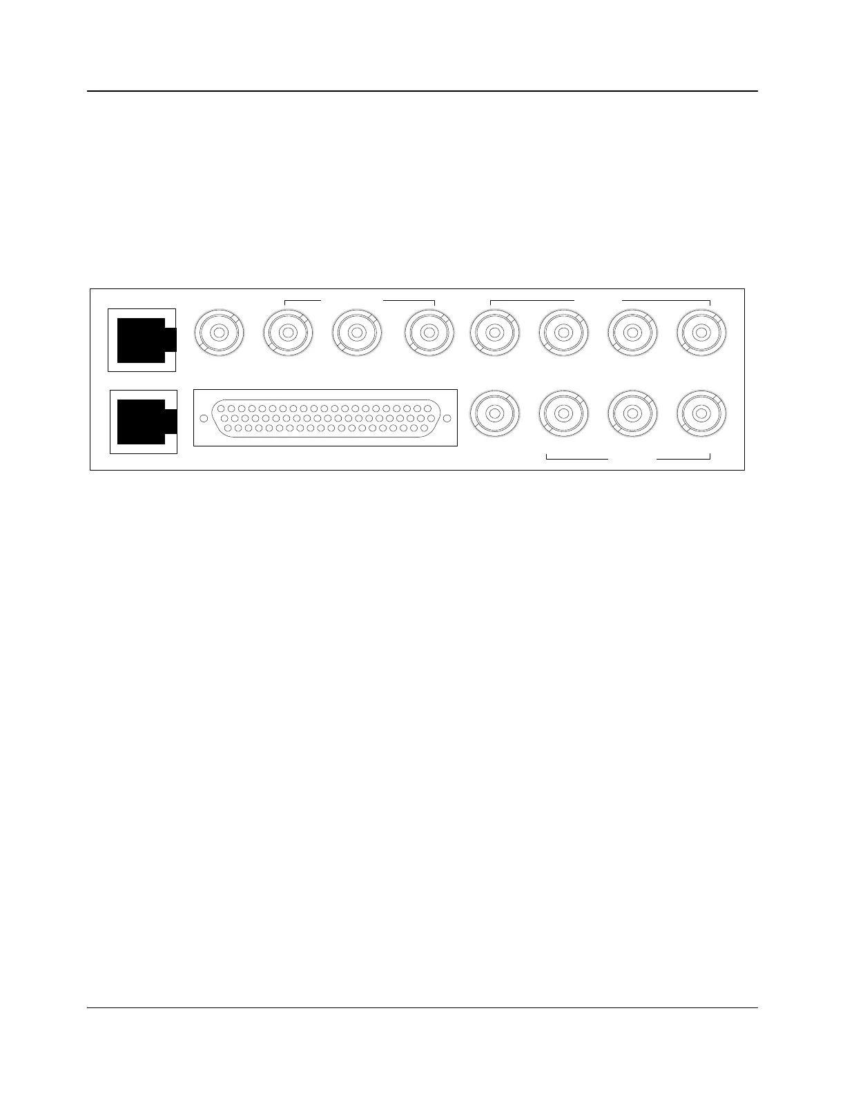
Figure 2-25 shows the back module of the MKE-3901 module. Make all
appropriate I/O connections as appropriate for your system setup. Specific
information concerning Ethernet, Genlock, Bus A and B, and multifunction I/O
connectors is provided below.
Figure 2-25. MKE-3901 Back Module
Ethernet
Use Ethernet 1 to connect the MKE-3901 to a network hub or directly to an
IconMaster control panel.
Use Ethernet 2 to connect the MGI-3903 to a network hub or directly to an
IconLogo control panel.
Genlock
The default Genlock Source Type is Composite. To change this setting, see the
Genlock dialog box in the IconMaster configuration utility software.
This input is terminated to 75Ω internally by default. See jumper J16 on page 34
if termination is not desired.
Multifunction I/O
The pin numbers for the Multi Function I/O connector, with corresponding
pinout information, are shown in Table 2-2 on page 39.
Bus A/Bus B Input Connectors
For information about Bus A and Bus B connectors, see “System
Configurations—NEO Routers” on page 77 and “System
Configurations—Panacea Routers” on page 91.
Genlock
Clean PGM PST
Squeeze
Bkgd
Bus A Key 1 Fill 2
Fill 1 Key 2Bus BPGM
MKE-3901-BM
Multi Function I/O
Outputs Inputs
Inputs
Output
Ethernet 1
Ethernet 2