IconMaster Installation and Configuration Manual 39
Chapter 2: Installation
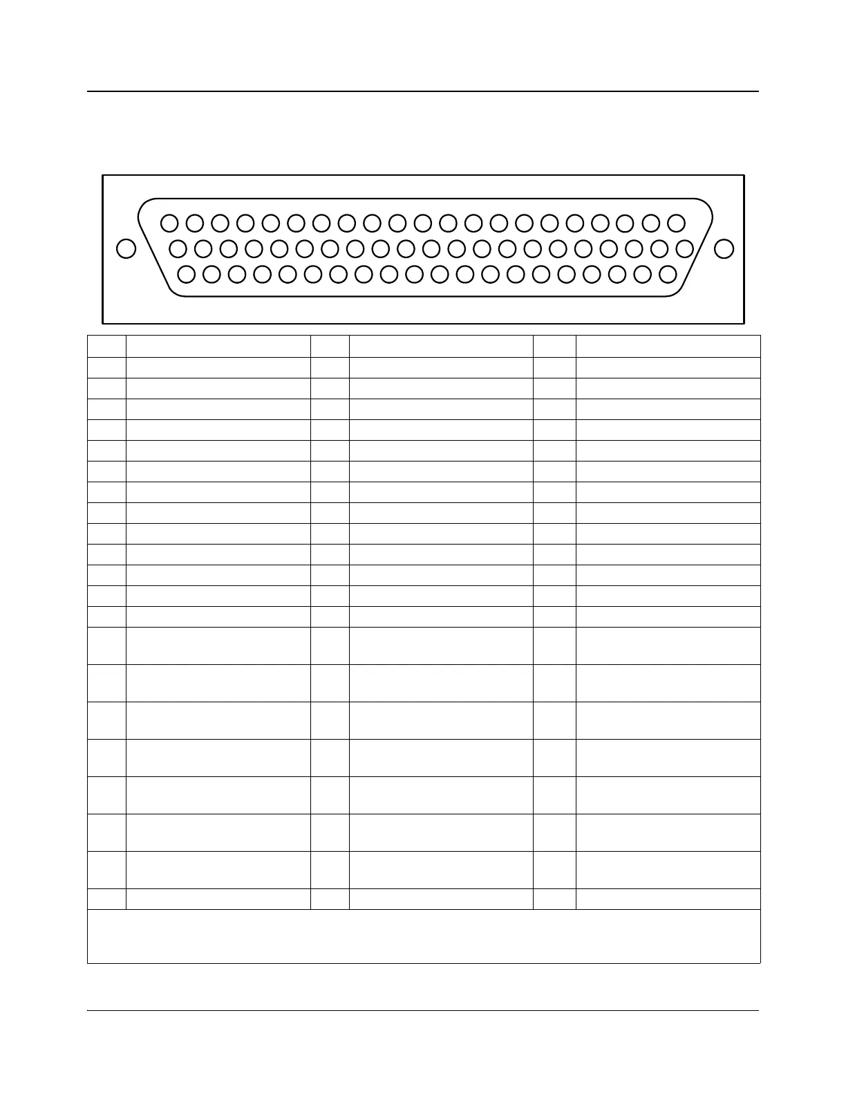
Table 2-2. MKE-3901 Multi-Function I/O Pinouts
This pinout information is for use when it is necessary to wire directly to the connector. If you are using a ICONM-BO-V
breakout module (shown in Figure 2-27 on page 43), this information is not required.
Pin Function Pin Function Pin Function
1 MKE AES A/O 2 (B+)* 22 MKE AES A/O 1 (B-)* 43 MKE AES A/O 1 (B+)*
2 Ground 23 MKE AES A/O 2 (B-)* 44 Ground
3 GPI 11 24 Ground 45 GPI 9
4 GPI 14 25 GPI 12 46 GPI 10
5 GPI 17 26 GPI 13 47 GPI 15
6 GPI 18 27 GPI 16 48 GPO 8
7 GPO 6 28 GPO 11 49 GPO 9
8 GPO 4 29 GPO 7 50 GPO 10
9 GPO 2 30 GPO 5 51 GPO 12
10 Bypass relay control 31 GPO 3 52 GPO 13
11 GPI 8 32 GPO 1 53 MGI LTC +
12GPI 433GPI 654MGI LTC -
13 GPI 7 34 GPI 2 55 MGI temperature sensor +
14 RS-232-B RxD or
RS-422-B RX -
35 GPI 5 56 MGI temperature sensor -
15 RS-232-B n/c or
RS-422-B RX +
36 GPI 3 57 RS-232-D RxD
16 RS-232-E TxD or
RS-422-E TX -
37 GPI 1 58 RS-232-D TxD
17 RS-232-E n/c or
RS-422-E TX +
38 Ground 59 RS-422-C TX -
18 RS-232-E n/c or
RS-422-E RX +
39 +5V** 60 RS-422-C TX +
19 RS-232-E RxD or
RS-422-E RX -
40 Ground 61 RS-422-C RX +
20 RS-232-B TxD or
RS-422-B TX -
41 RS-232-B n/c or
RS-422-B TX +
62 RS-422-C RX -
21 RS-232-A RxD 42 RS-232-A TxD
*Audio Over 1 and 2: For balanced data, use B+ and B-. For unbalanced (coax), use B+ for the signal and connect B- to
ground (shield). There are also jumpers on the MKE card, which must be set to indicate balanced or coax.
**Reserved for bypass relay operation.
42
21
62
20
41
61
19
40
60
18
39
59
17
38
58
16
37
57
36
15
56
14
35
55
13
34
54
12
33
53
11
32
52
10
31
51
30
9
50
8
29
49
7
28
48
6
27
47
5
26
46
4
25
45
24
3
44
2
23
43
1
22