28 IconMaster Installation and Configuration Manual
Chapter 2: Installation
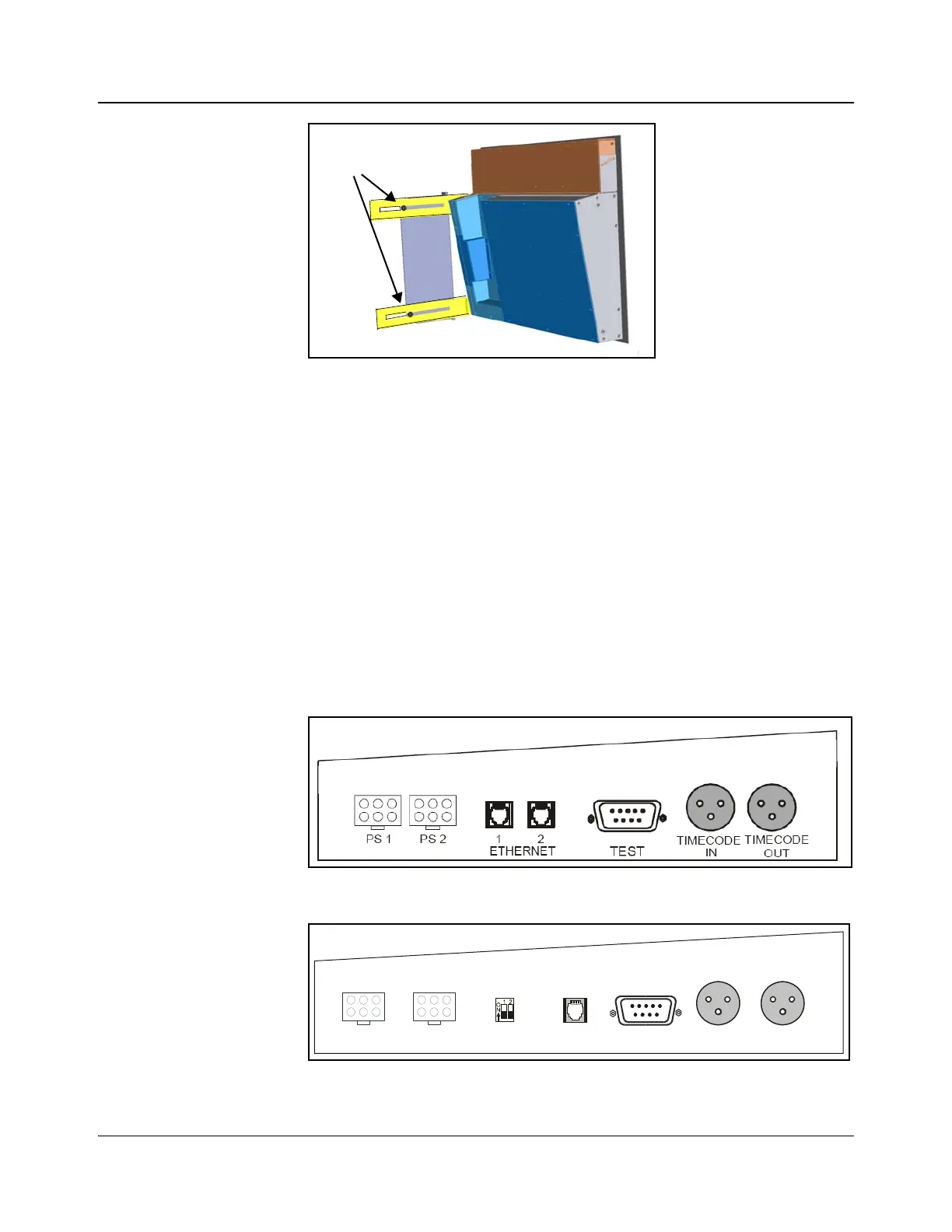
Figure 2-14. Adjustment of Slider Screws
8. Tighten the slider screws and make all of the necessary cable connections
on the back of the main control panel.
9. Align the control panel assembly so that the screw holes in the mounting
brackets match up with those at the front of the rack.
10. Secure the control panel assembly to the rack with 10×32 machine-head
mounting screws and washers.
11. Make necessary control panel connections (see page 28).
Connecting Main Control Panel Components
The IconMaster main control panel has external connections located in a bay on
the underside of the unit (Figure 2-16). In addition, two 50-pin connectors at the
back of the panel provide an interface with the optional audio control panel.
Figure 2-15. Main Control Panel External Connections—Older Models
Figure 2-16. Main Control Panel External Connections—Newer Models
Tighten screws at
the back of the
slider
ETHERNET
TIMECODE
OUT
PS 1 PS 2
TIMECODE
IN
TEST
LTC/
FAILSAFE