IconMaster Installation and Configuration Manual 29
Chapter 2: Installation
The Timecode IN provides a means for IconMaster to read a facility time-of-day
real-time clock. If desired, feed a unity speed, forward counting LTC timecode
signal into the Timecode IN connector, and configure the IconMaster to use the
RCP panel as it's primary time-of-day clock source. A Harris MTG-3901
module or CSD5300 product can be used for this timecode signal. DIP Switch
1 (below) is used to set the Timecode IN termination to either open or 600Ω.
See page 206 to setup IconMaster to use the RCP's Timecode IN as the real-time
clock source.
One RCP panel can be setup as the real-time clock source for
multiple IconMaster channels.
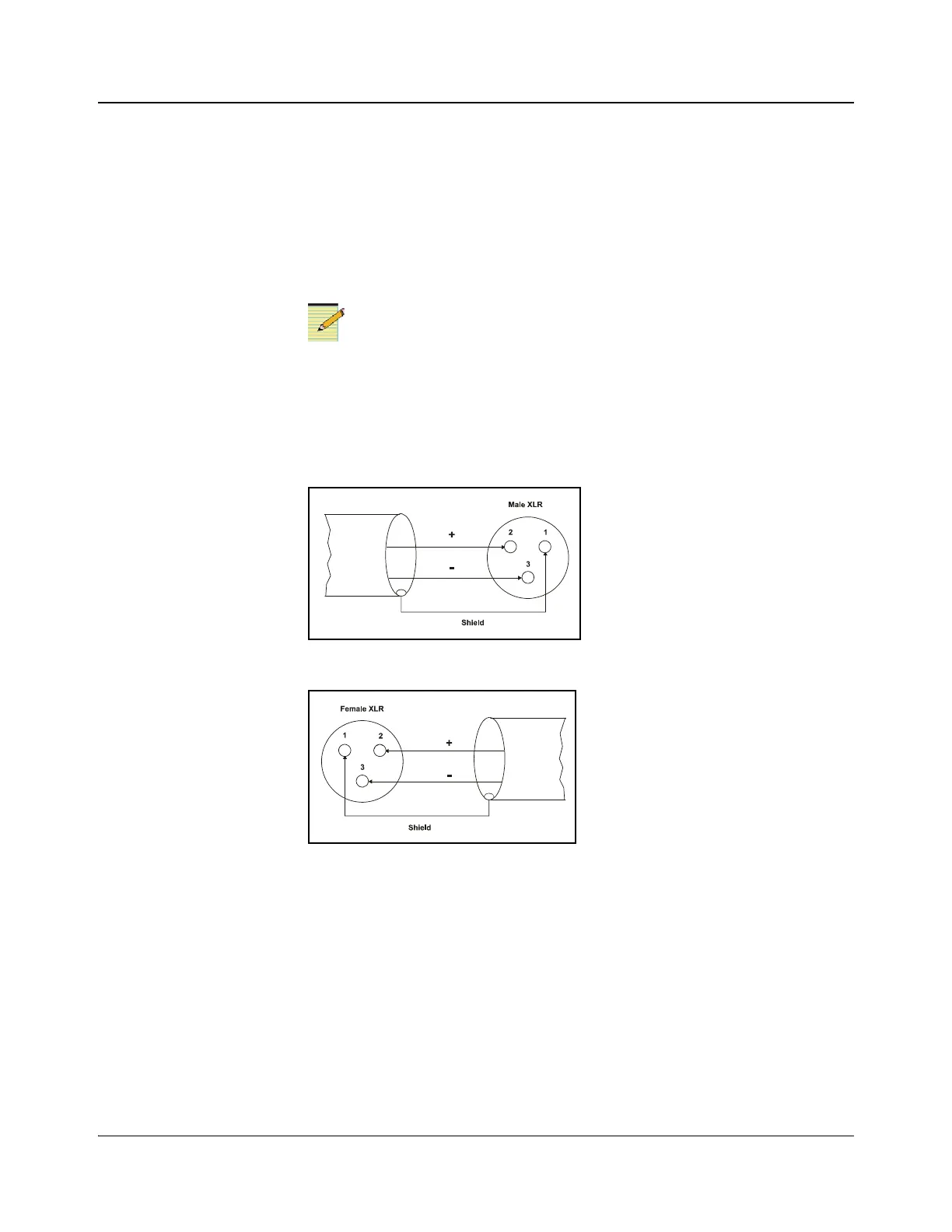
The Timecode OUT connector is used to feed an external LTC timecode display
device with a time function from the IconMaster. IconMaster can display either
the time-of-day or its segment timer on this output. See page 206 to set this up.
Figure 2-17. Timecode IN (Rear Panel View)
Figure 2-18. Timecode OUT (Rear Panel View)
DIP Switch Settings
The DIP switches on the main control panel allow you to set values for
termination for timecode in (LTC) and for failsafe bootloader (CPU BOOT).
DIP switch 1 controls the LTC setting and DIP switch 2 controls the CPU
BOOT setting. See Figure 2-19 on page 30 for the values of these settings.