80 IconMaster Installation and Configuration Manual
Chapter 4: Router Connections
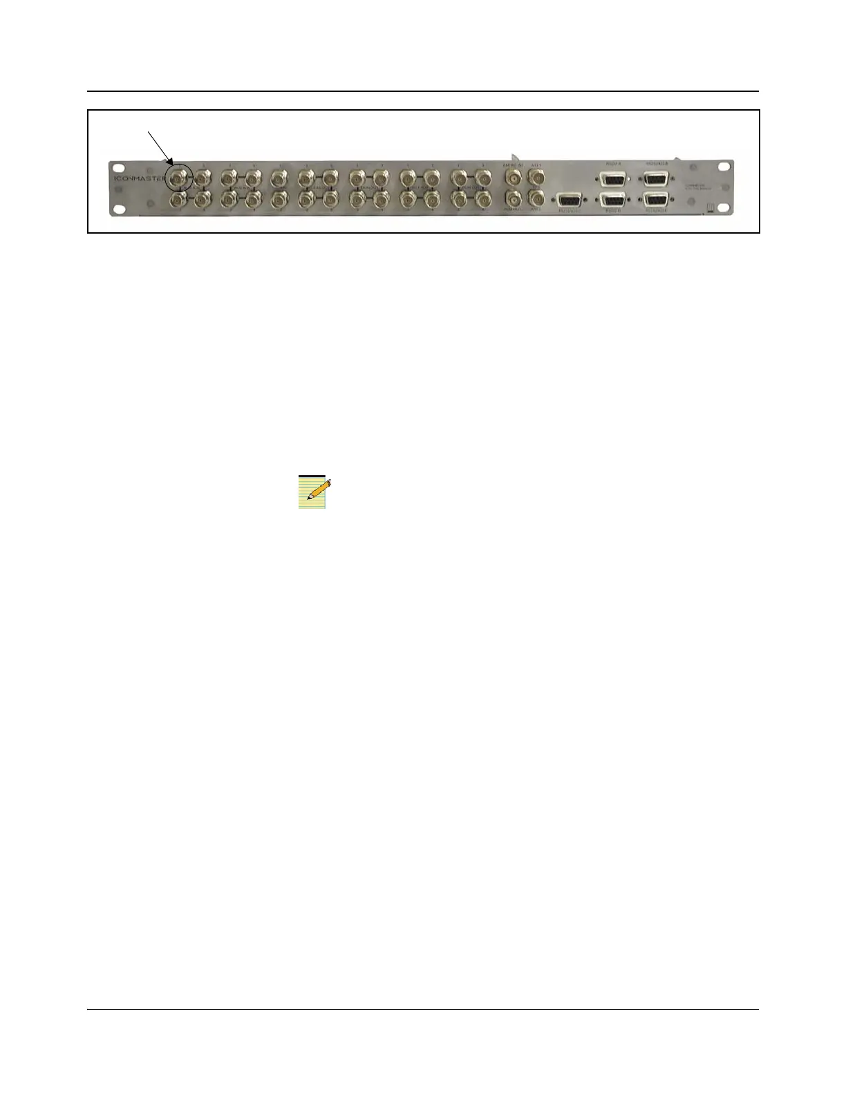
Figure 4-4. Audio 1 NSM Connection to ICONM-BO-VAC
2. Make Additional Connections
1. Connect your composite station reference to the Ref Inputs and Genlock
connection as shown in Figure 4-3.
2. On the MKE-3901 back module, connect Key 1 input source to Key 1 and
Fill 1 as appropriate.
3. On the MKE-3901 back module, connect Key 2 input source to Key 2 and
Fill 2 as appropriate.
On the MKE-3901 back module, Squeeze Bkgd can be supplied by an
external router.
4. Connect the two Ethernet ports as follows:
Connect Ethernet 1 (connection for MKE-3901 control) to a switch using a
straight-through Ethernet cable.
Connect Ethernet 2 (two connection options for MGI-3903 control and
logo download)
• To the same switch as Ethernet 1 using a normal Ethernet cable
• To a dedicated switch used for the MGI functionality using a normal
Ethernet cable
5. Power up the system.
3. Set the IP Address for the MKE-3901 Module
1. Press the left (Esc) button until the message MKE3901 appears on the VFD
display.
2. Press the right (Enter) button.
3. Use the toggle switch (Nav) to scroll through the parameter list until Status
is highlighted.
4. Press the right (Enter) button.
5. Use the toggle switch (Nav) to scroll through the parameter list until Other
is highlighted.
The IconMaster control panel can be connected to any network
switch that shares a network with the MKE-3901 and MGI-3903
modules.