94
Motor Measurement (Motor Analysis-Equipped Model)
When [Motor analysis option wiring] is set to [Torque Speed Direction Origin] or
[Torque Speed Origin] and the synchronous sources from Ch. 1 to Ch. 8 are set to [Zph1] or
[Zph3], the measured voltage and current based on one motor spinning (one mechanical angle
cycle) are displayed.
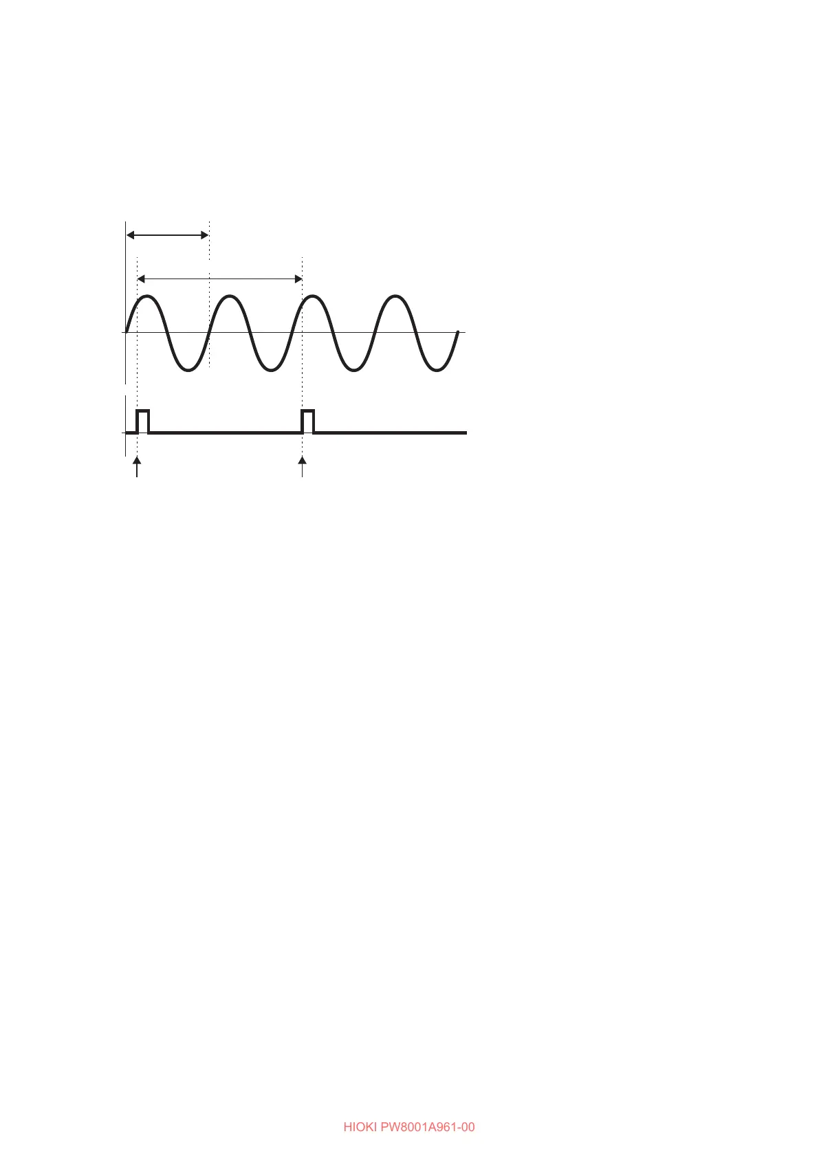
Example for a 4-pole motor
External synchronization
signal (Z-phase)
Calculation period
Fundamental wave frequency (U1)
Reference Reference
• To use a rising edge of the external synchronization signal (Z-phase) as the reference, set the
Z-phase reference to Rising; to use a falling edge, set to Falling.
• Since one motor rotation is always used as the calculation range regardless of the number of
poles the motor has, measurement can be performed by averaging the variations for each pole
that are caused by the motor’s mechanical characteristics.
• For measured values of voltage and current harmonic values, measured values of fundamental
wave appear as the order of half the number of motor poles. Subsequently, the nth-order
harmonics of voltage and current appear at the product of half the number of motor poles and n.
• The voltage and current fundamental frequencies are measured to obtain measured voltage and
current frequency values.
• Provide input as appropriate based on measurement parameters of Ch. A through Ch. D or Ch. E
through Ch. H. In addition to inputting the origin signal to Ch. D or Ch. H (Z-phase pulse), the
rotation signals need to be correctly inputted to Ch. B or Ch. F (A-phase pulse) and Ch. C or
Ch. G (B-phase pulse when the direction is used).
• To use other pulses as the calculation scope’s reference instead of pulses outputted from a rotary
encoder, you are recommended to use in [Indiv.] operating mode of the motor analysis and
set the synchronization source of input channels 1 through 8 to Ch. B, Ch. D, Ch. F, or Ch. H,
respectively. Input the reference pulses as the selected synchronization source.

 Loading...


