93
Motor Measurement (Motor Analysis-Equipped Model)
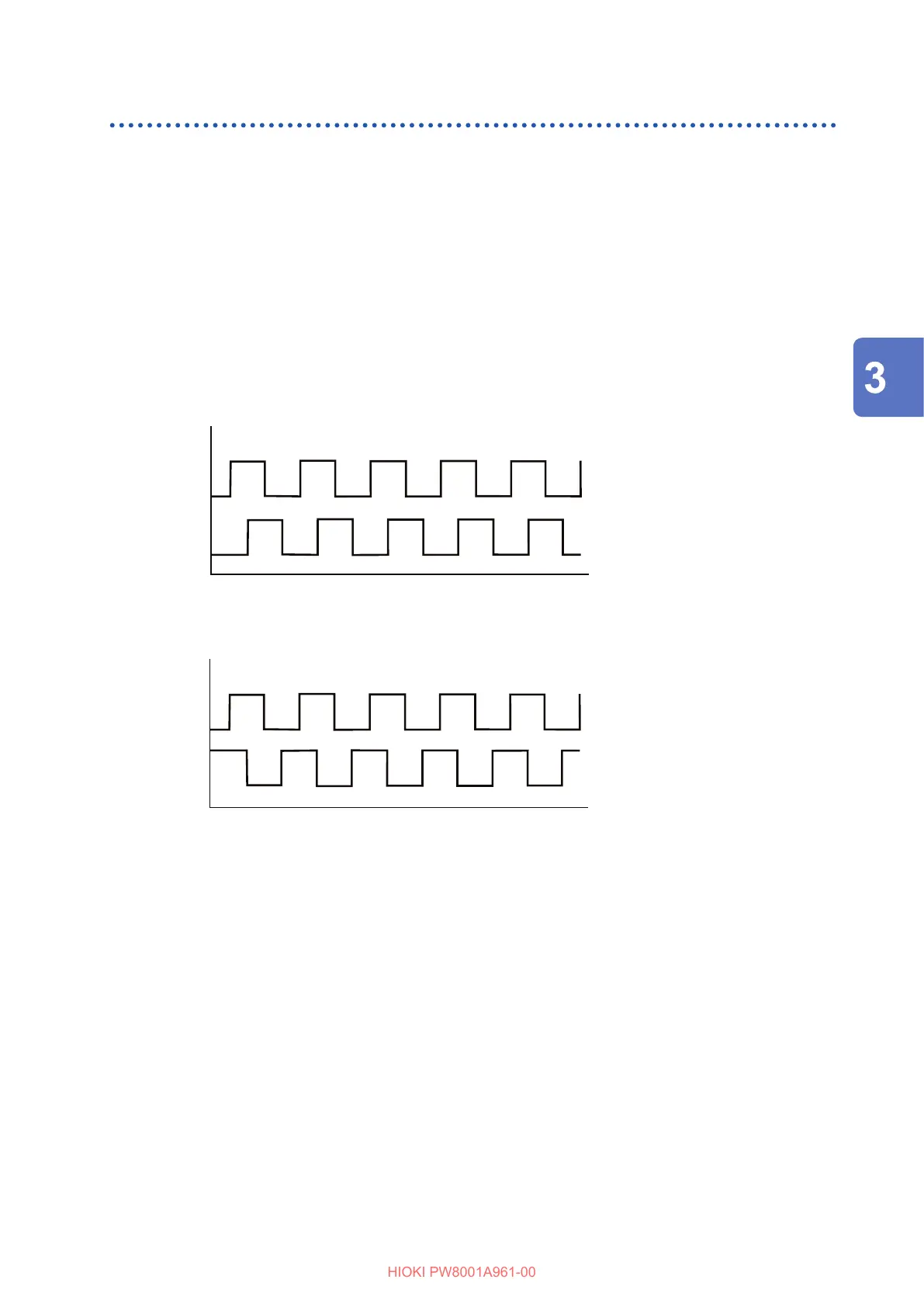
Detecting the motor’s direction of rotation
If an incremental-type rotary encoder’s A-phase pulse and B-phase pulse are inputted to Ch. B
and Ch. C input terminals or Ch. F and Ch. G input terminals, which are for the rotation signals, the
instrument can detect the direction in which the shaft is rotating, assigning a corresponding polarity
sign to the RPM values.
When [Motor Analysis option wiring] is set to [Torque Speed Direction Origin] or
[Torque Speed Direction], the direction of rotation can be detected.
Direction of rotation is judged based on the level of the other’s pulse (high/low) when rising and
falling edges of the A-phase and B-phase pulses are detected.
Forward operation
RPM polarity: plus sign (+)
A-phase
B-phase
Backward operation
RPM polarity: minus sign (−)
A-phase
B-phase
The detected direction of rotation aects the polarity sign assigned to measured RPM values as
well as measured motor power (Pm) values.
Displaying Power Numerically

 Loading...


