81
Motor Measurement (Motor Analysis-Equipped Model)
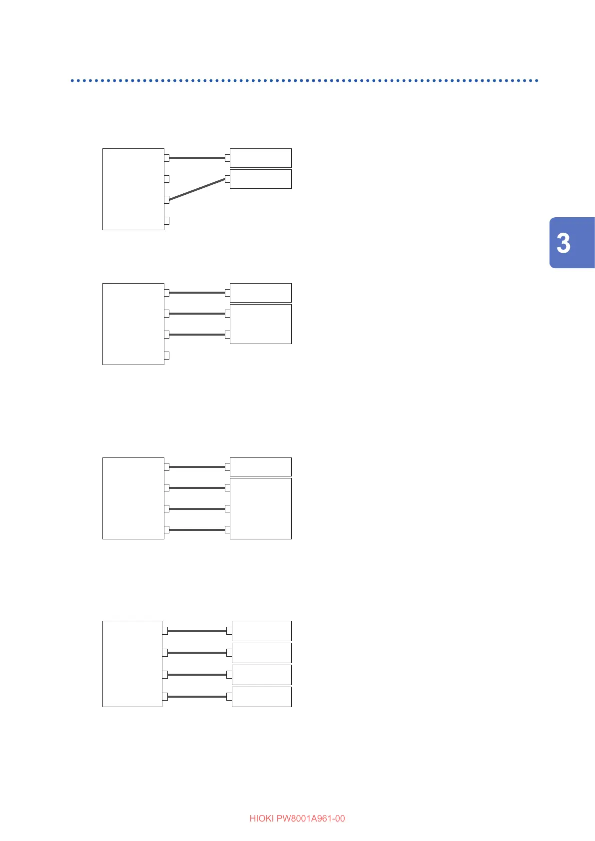
Connection examples of motor analysis
In these examples, a torque meter and a tachometer are being connected with Ch. A to Ch. D.
You can connect them to Ch. E through Ch. H as well.
Example 1: Motor power measurement (settings of motor analysis mode pattern 5)
Ch. A or Ch. E
Ch. B or Ch. F
Ch. C or Ch. G
Ch. D or Ch. H
Torque output
RPM output
Input the torque signal to Ch. A and the RPM signal
to Ch. C. Then measure the motor power and motor
eciency.
The torque signal can use an analog DC signal or pulse-
based frequency input.
The RPM signal must be an analog DC signal.
The torque signal and RPM signal can be inputted from
dierent sensors.
Example 2: Motor power measurement with forward/reverse detection
(setting of motor analysis mode pattern 3)
Torque output
Ch. A or Ch. E
Ch. B or Ch. F
Ch. C or Ch. G
Ch. D or Ch. H
A-phase
pulse output
B-phase
pulse output
Torque output
Input the torque signal to Ch. A, the A-phase pulse signal
to Ch. B, and the B-phase pulse signal to Ch. C. Then
measure the motor power and motor eciency while
viewing the direction of the motor’s rotation based on
the phase dierence between the A-phase pulse and the
B-phase pulse.
The torque signal can use an analog DC signal or pulse-
based frequency input.
Example 3: Motor power measurement with electrical angle measurement
(settings of motor analysis mode pattern 2)
Ch. A or Ch. E
Ch. B or Ch. F
Ch. C or Ch. G
Ch. D or Ch. H
Torque output
A-phase
pulse output
B-phase
pulse output
Z-phase
pulse output
Input the torque signal to Ch. A, the A-phase pulse signal
to Ch. B, the B-phase pulse signal to Ch. C, and the
Z-phase pulse (origin) signal to Ch. D. Then measure the
motor power and motor eciency while measuring the
electrical angle.
By setting the synchronization source to Zph., you can
synchronize measurement to the mechanical angle
instead of the electrical angle.
The torque signal can use an analog DC signal or pulse-
based frequency input.
If you do not need to detect the direction of the motor’s
rotation, it is not necessary to input the B-phase pulse to
Ch. C, and you can select pattern 4 instead.
When using Zph. as the synchronization source, you
need to input not only the Z-phase pulse to Ch. D, but
also the A-phase pulse to Ch. B.
Example 4: Motor power measurement (settings of motor analysis mode pattern 1)
Ch. A or Ch. E
Ch. B or Ch. F
Ch. C or Ch. G
Ch. D or Ch. H
Torque output
RPM output
Torque output
RPM output
Input the torque signal and the RPM signal to Ch. A and
Ch. B to measure the motor power and motor eciency
of the rst system. Input the torque signal and the RPM
signal to Ch. C and Ch. D to measure the motor power
and motor eciency of the second system.
The torque signal can use an analog DC signal or pulse-
based frequency input.
Only pulse-based RPM signal can be input.
Conguring connected motor input settings and displaying measured values
For details about the display of measured values and the settings for inputting signals, see “3.6
Motor Measurement (Motor Analysis-Equipped Model)” (p. 78).
Displaying Power Numerically

 Loading...


